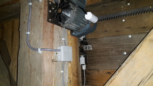
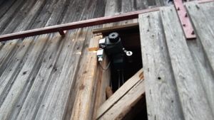
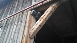
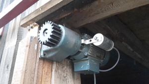
An old sliding gate got upgraded with electric motors - Rework after 7 years
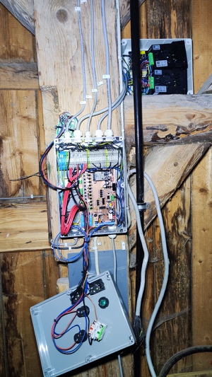
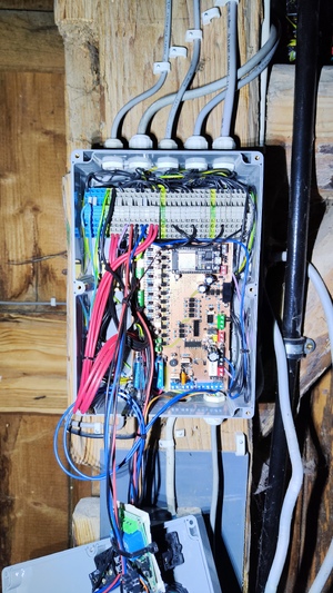
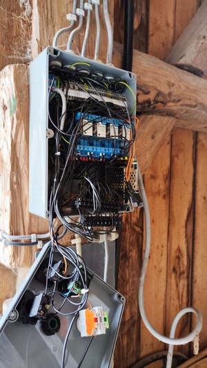
The original automated sliding gate project, built in 2018, has been completely reworked after 7 years of use. While the motors and wiring remained the same, the control system was redesigned from the ground up.
V1 Performance & Lessons Learned
The original built system performed pretty reliable for 7 years, making daily life much easier. However, over time, a few issues and missing features became apparent:
- Startup stress – Motors engaged too abruptly, wearing gears, racks and mounts
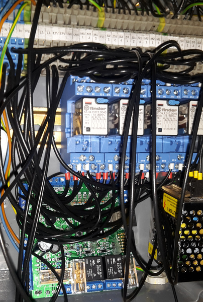
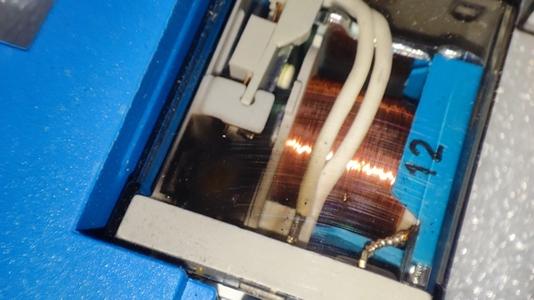
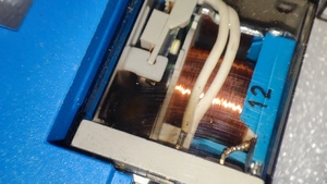
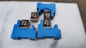
- Relay wear – 12V relays degraded, causing unreliable operation
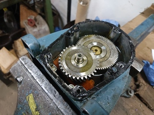
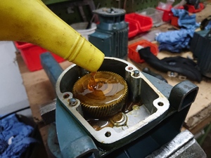
- Cold start issues – Thickened gearbox grease in the winter prevented movement due to weak starting torque
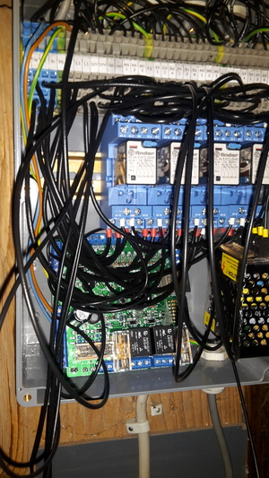
- EMI problems – Sparks from relays forced external PCB placement
- Limited control – No acceleration and torque control, or overload detection
- Missing safety features - insufficient light barrier, no locking mechanism
V2 addresses these with a custom PCB and VFD-based motor control, improving reliability and adding new features.
What’s New in V2
-
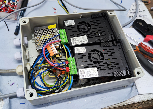
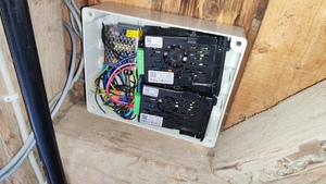
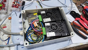
VFD-controlled motors instead of relays and capacitors
- Smooth starts
- Precise speed and torque control
- Overload detection
-
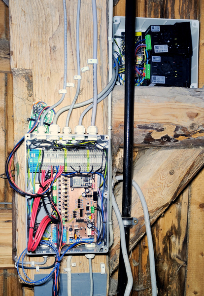
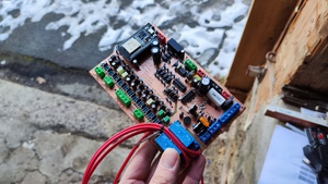
Custom PCB
- Isolated microcontroller from long cables & VFD noise
- Integrated RS485 interface
- Servo interface for gate locking
- Encoder support for precise position tracking
-
New features & planned upgrades
- Multiple Light barriers
- Overload detection
- Servo motors for locking the gate
- Actual position tracking using encoders
Specification
- Power supply: 230 V AC
-
Control Interfaces:
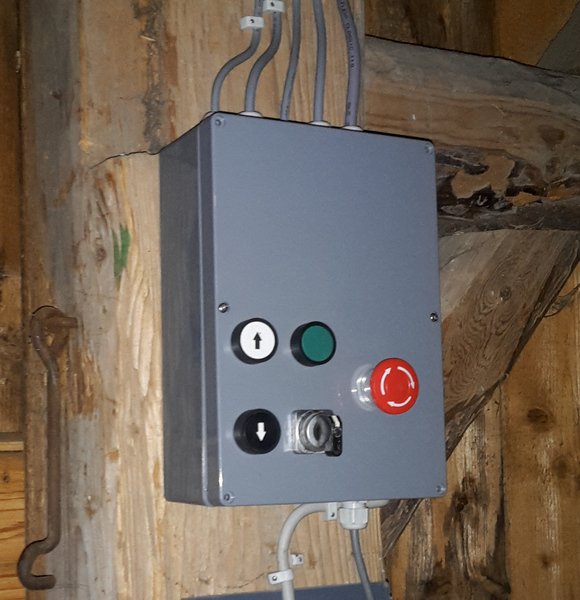
- Buttons on gate
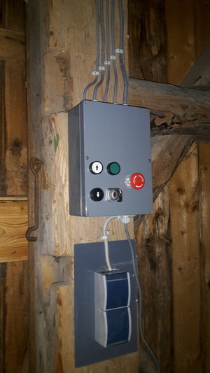
- Buttons on control box
- Remote control (radio transmitter)
Web interface
- Open / Closing speed: adjustable from 0 to 2 m/s
Components
Mechanical
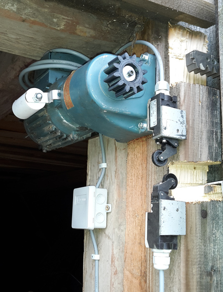
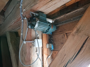
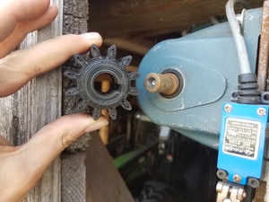
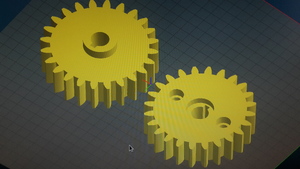
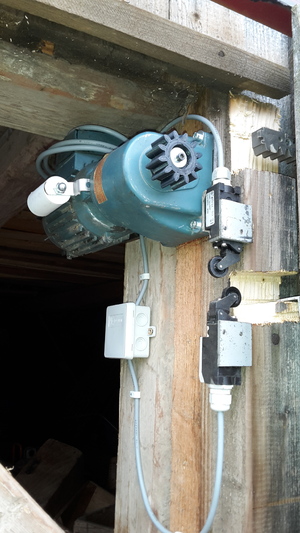
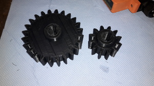
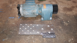
- 2x 3D-printed gear
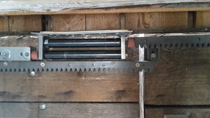
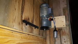
- 2x Toothed rack
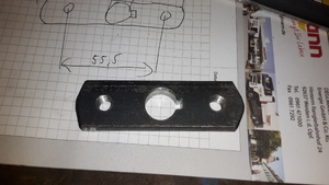
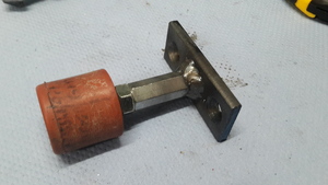
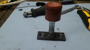
- 4x Custom end position damper
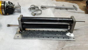
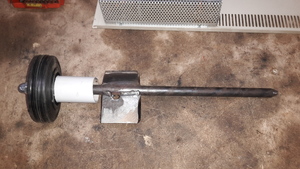
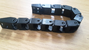
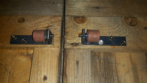
- 2x Custom guide roller
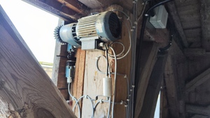
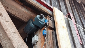
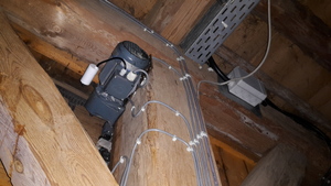
Motors
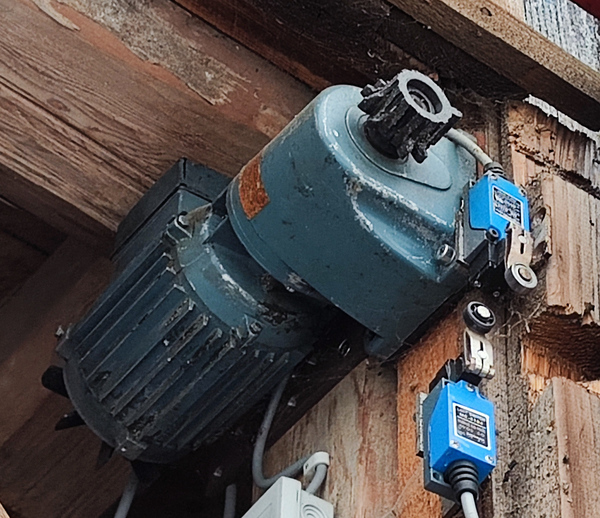
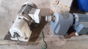
- Power: 0.3 kW
- Voltage: 400 V
- Frequency: 50 Hz
- Type: Three-phase asynchronous motor
- Connection: Now VFD-controlled (previously capacitor-based)
Control System
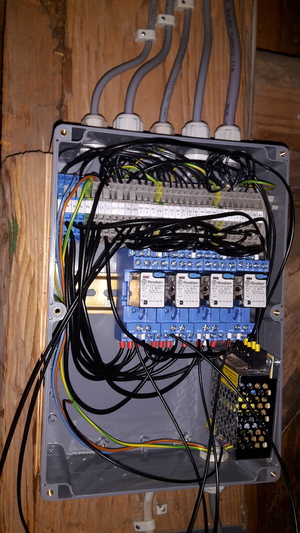
- Custom PCB with ESP32 microcontroller
- Motor control via VFDs (instead of relays)
- Sensors:
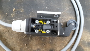
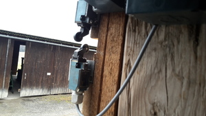
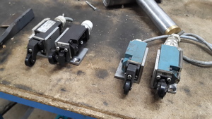
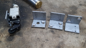
- Limit roller switches
- Photoelectric barrier (new in V2)
- Encoders tracking motor position
- Servo-controlled locking mechanism (new in V2)
- RS485 interface (new in V2)
Electrical Overview
The wiring of all components is documented in the following diagram:
Full Document: V2.0_wiring-plan.pdf
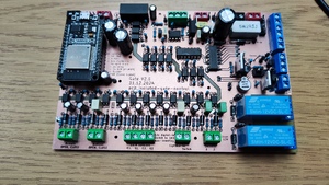
Control PCB
The custom PCB and firmware are available here: GitHub/gate_fw.
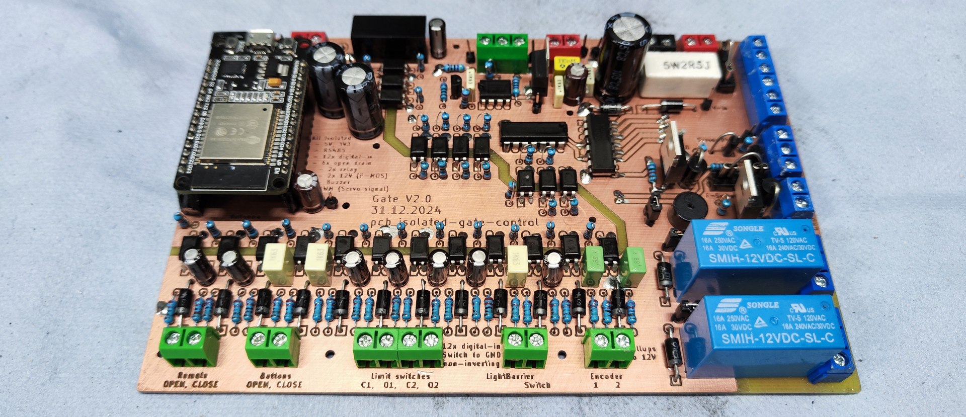
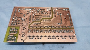
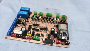
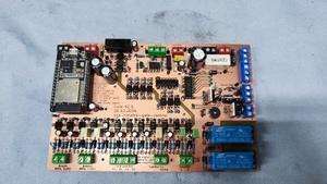
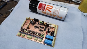
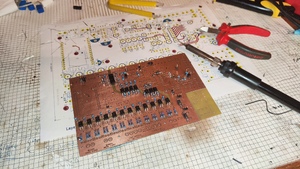
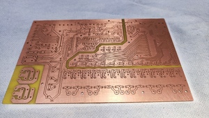
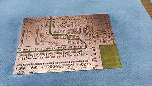
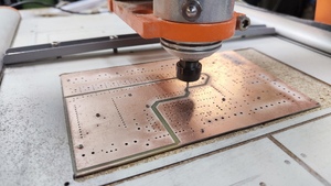
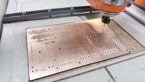
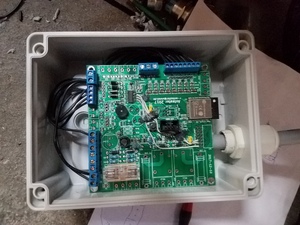
Designed specifically for this project, the PCB replaces the previous multipurpose board. It was CNC-machined for quick availability. The core features are:
- Optical isolation of the microcontroller
- EMI safe using integrated filters and protection
- Isolated RS485 interface for controlling the VFDs
- Built-in servo control
Schematic
Complete Schematic: schematic.pdf
Layout
3D Model
Firmware
The Firmware and the PCB design are versioned and available in the repo Github/gate_fw. The ESP32 was programmed in C++ using ESP-IDF.
Videos
(New videos with V2 coming soon)
First Open (Old System)
2018.02.06
First Close (Old System)
2018.02.06
