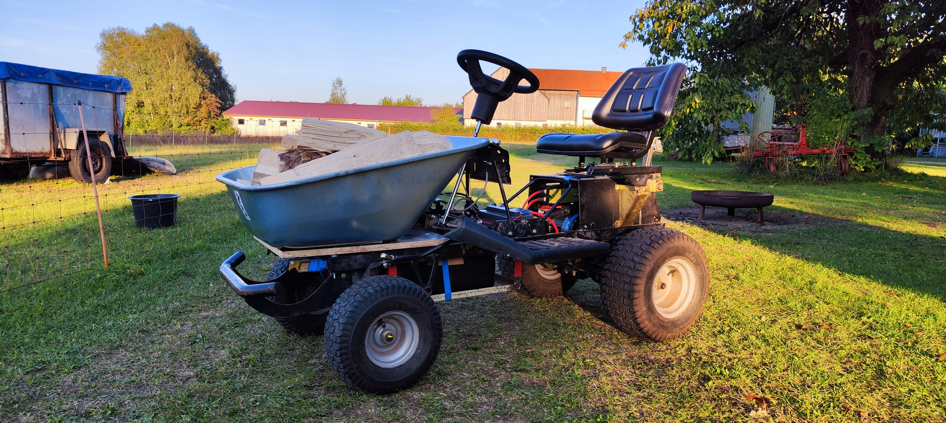
Transforming an old lawn tractor into a versatile electric vehicle for practical yard work.
This project focuses on converting a decommissioned damaged lawn tractor into an electric machine designed for various tasks, from towing trailers to carrying loads, with multiple attachments planned.
Motivation
The engine of a 10-year-old lawn tractor was damaged beyond repair and a new tractor purchased. Rather than simply discarding the old tractor, this project was born to use the chassis and transmission of the tractor and convert it into a versatile electric vehicle for use around the garden, giving it a new purpose.
 New and old lawn tractors
 Lawnmower frame as base for this project
 Shattered connecting rod parts
 Hole in engine block
Specification
-
Top speed:
- Theoretical: 34 km/h (6500 rpm with flux weakening)
- Practical: ~25 km/h (limited by chassis stability)
- Range: ~30-40 km (estimated: 3.9 kWh usable, 100-130 Wh/km)
-
Current Features:
- 90 L utility tray
- Bicycle trailer hitch
- 230 V outlet (sine wave inverter, 2200 W continuous / 4400 W peak)
- Water pump attachment
-
Future Features (Work in Progress):
- Sweeper attachment
- Snow plow
- Tiltable utility tray
- Lights
Note: A lawn tractor chassis is not built for these speeds: the steering gets unstable and the front lifts easily under full torque. The power reserve is meant for towing and attachments, not for speed.
 Parked vehicle
Components
Mechanical
- Frame: From lawn tractor Iseki CM 7226 H
-
Drivetrain:
- Custom intermediate shaft connecting motor to old hydrostatic transmission, utilizing the differential
- Timing Belt Drive:
- Motor Pulley: 8M Z22 20 mm
- Shaft Pulley: 8M Z56 20 mm
- Belt: HTD 8M Timing Belt 20mm 656 mm (Z82)
- Chain Drive:
- Shaft Sprocket: Z15
- Gearbox Sprocket: Z18
- Chain: 06B-1 (3/8″ × 7/32″)
- Gearbox:
- Spur Gear (Shaft with sprocket for chain): Z10
- Differential Spur Gear: Z54
- Total reduction: 16.5 : 1
- Rear tires: 18x8.50-8 (Ø 457 mm)
-
Brakes:
- 2 Disk Hydraulic Brake Set for ATV
- Custom adapter for attaching brake disk to rim
 Custom drivetrain
 Original hydrostatic transmission with differential
 Custom drivetrain parts before assembly
Motor
Chosen as a complete, matched kit (motor, controller, throttle) with plenty of reserve, so the vehicle is never underpowered - even when pulling heavy trailers or with future attachments.
- Name: QS Motor QS138 90H (version without gearbox)
- Type: PMSM, inner rotor, air-cooled
- Pole pairs: 5
- Rated voltage: 72 V
- Power (mechanical):
- Rated: 4 kW
- Max. continuous: 7.5 kW
- Peak: 13.5 kW
- Torque:
- Rated: 14.3 Nm
- Peak: 72 Nm
- No-load speed at 72 V: 4000 rpm (6500 rpm with flux weakening)
- Max. DC bus current: 200 A
- Max. efficiency: 94 %
- Sensors: Hall (rotor position), KTY83/122 (winding temperature)
- Weight: 13 kg
- Price: 350 EUR
Manufacturer test report
(~70 V DC, phase current limited to 300 A rms):
- Max. torque: 60.6 Nm at 1315 rpm
-> torque constant ≈ 0.2 Nm/A (rms) - Max. power: 10.0 kW at 4270 rpm (94.6 % efficiency incl. controller)
 Open motor + replacement motor
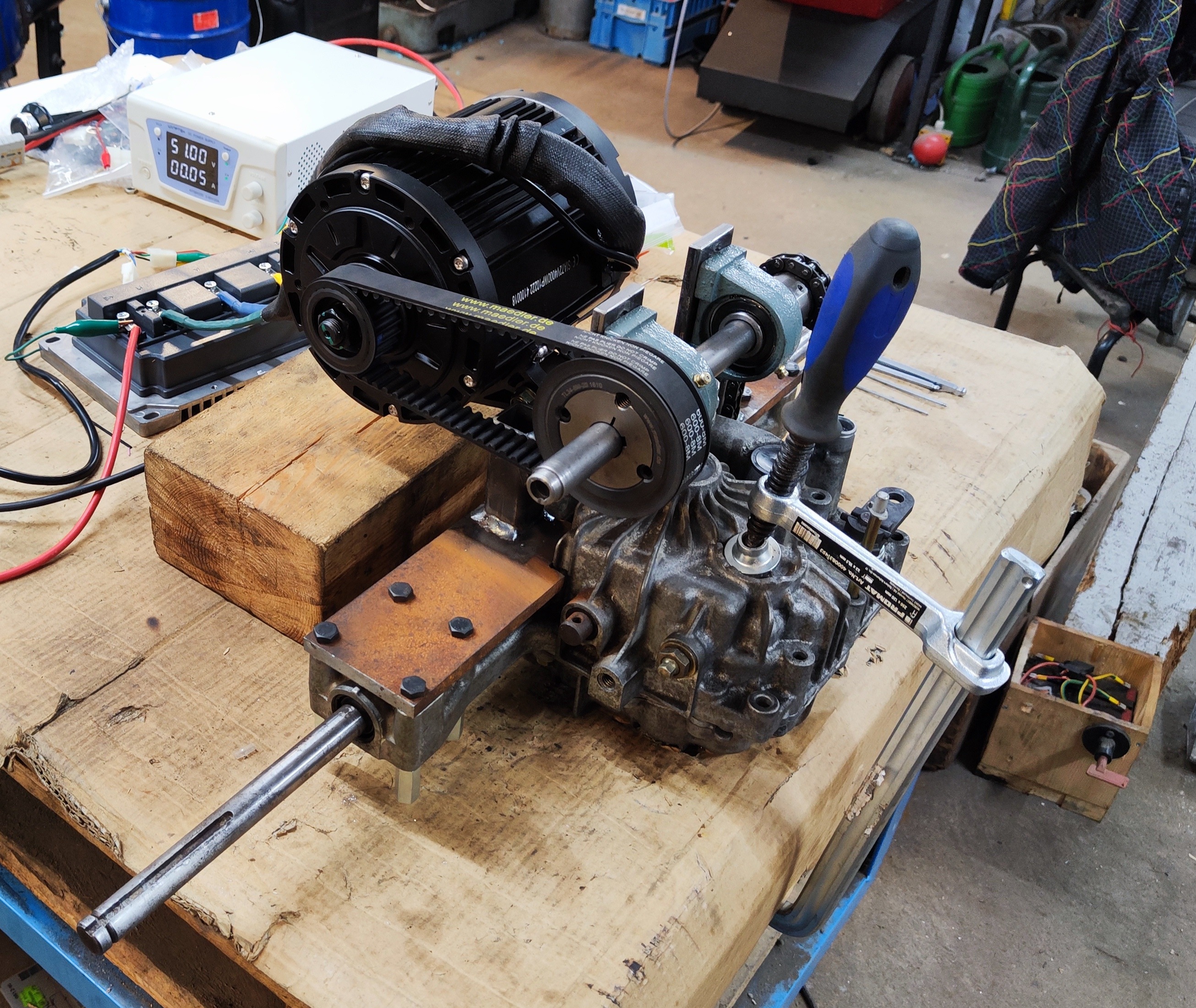 Workshop test of motor, belt drive, intermediate shaft and gearbox (initial belt ratio)
Controller
- Name: Votol EM200-2SP
- Rated voltage: 72 V
- Max. DC current: 200 A
- Max. phase current: 600 A
- Max. power: 18 kW (at 90 V)
- Configured limit: 85 A DC (100 A in sport mode) -> ≈ 6-7 kW
- Weight: 2.4 kg
- Efficiency: 92 %
- Price: 360 EUR
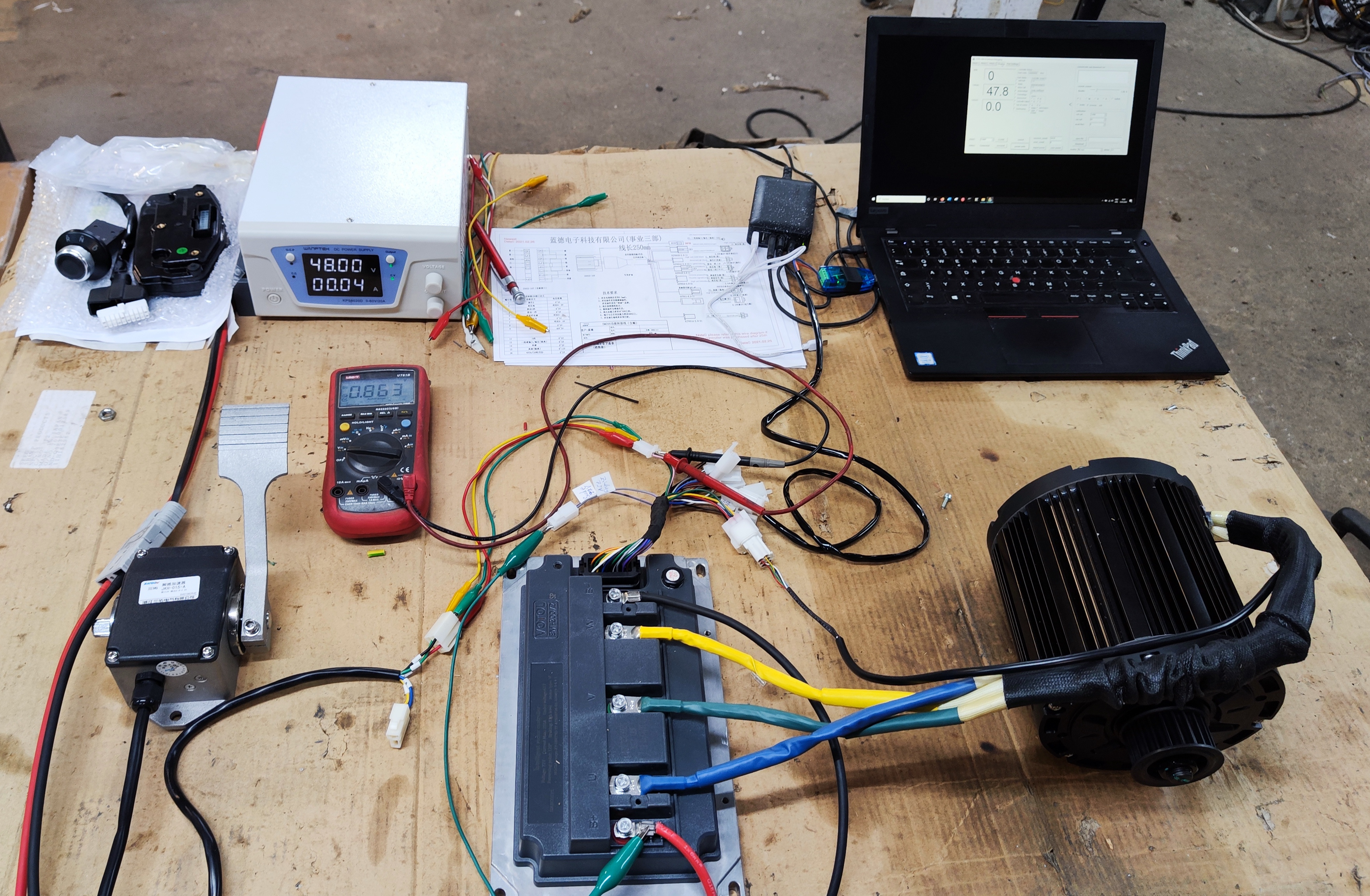 Test setup for controller programming
Battery
-
Stats:
- Rating: 72 V, 60 Ah (4.3 kWh)
- Cell arrangement: 20S 24P (480 Cells)
- Charge Voltage: 84 V
- Charge current: 15 A (1200 W)
- Type: Two bought Li-ion packs modified with custom BMS
- Battery cell: SINC ISR18650 2600
-
Original Pack:
- Rating: 72 V, 30 Ah, 2160 Wh
- Max current:
- Discharge: 60 A
- Charge: 5 A
- Cell arrangement: 20S 12P
- Price: 750 EUR
Note: I bought two of the original packs and rewired them in parallel for higher current output and to enable regenerative charging, as the original split-port BMS didn’t support parallel connection or regenerative braking.
-
Battery management system (BMS):
- Manufacturer: Daly
- Name: Smart BMS BT+CAN+WIFI 8-24S 150A
- Max current:
- Discharge: 150 A
- Charge: 100 A
- Type: Any cell type, Arrangement 8 to 24S
- Features:
- Over charge protection
- Over discharge protection
- Over current protection
- Balancing
- All values adjustable via app
- Price: 105 EUR
 One of the two bought packs already dismantled
 Dismantled batteries with wires soldered for connecting in parallel
 New 150 A BMS integrated
Technical Drawings
All 3D-printed parts, like the PCB housing and chain cover, were designed in FreeCAD and printed. Some metal parts, like the brake system, were also designed beforehand to serve as guides for manufacturing:


Difficulties
Motor Defect
Problem:
During the first few test runs, the motor started vibrating abnormally and overheated quickly. After trying various controller settings and running diagnostics, I decided to open the motor. It turned out that several windings were burnt and partially shorted.
Each phase winding consists of several insulated wires in parallel, which are only joined in the crimped cable lug at the controller. Where the insulation between these parallel wires failed, they formed a closed loop: every revolution the magnets induced a high current in it, flowing out through the phase cable to the lug and back into the motor. This constantly braked the motor and caused excessive heat, even without load.
The cause appeared to be loose windings and vibrations that wore down the insulation on the windings, leading to shorts.
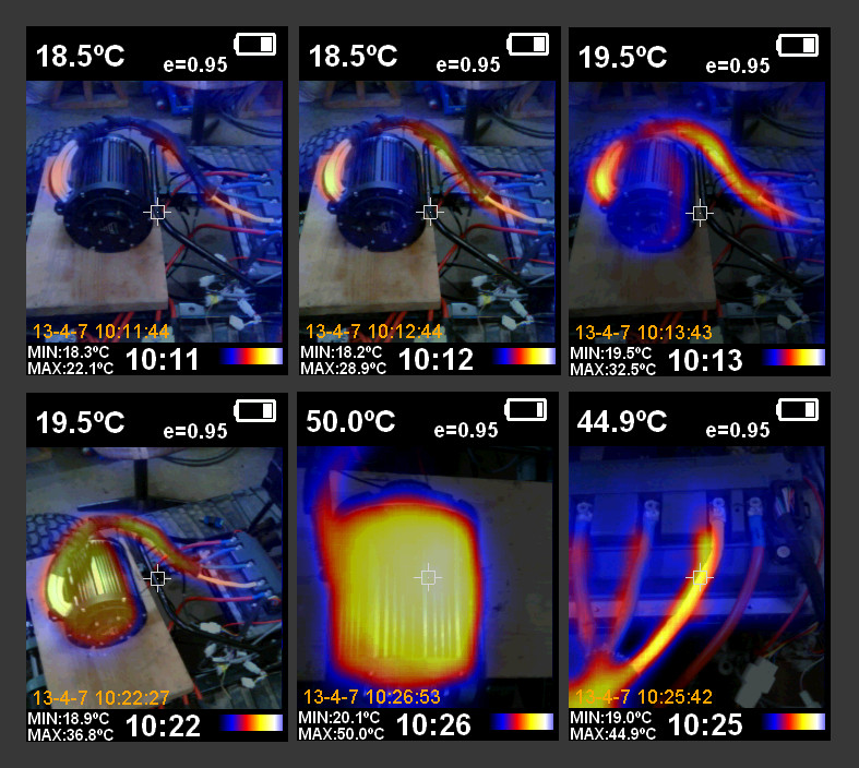 Thermal images to locate the fault. The motor heated up on one side first and only one phase cable got hot (path of the induced circulating current)
 Open rear side of the motor
 Close-up of the damaged motor windings
Solution:
QS Motor kindly provided a free replacement for the faulty motor.
While waiting for the new motor to arrive, a smaller temporary motor was installed to keep the vehicle functional during the debugging period. This 3 kW go-kart motor overheated quickly under continuous load, confirming that a smaller motor would have been too weak.

Bad Motor Controller
Problem:
The motor controller for the smaller BLDC motor, used temporarily while waiting for the replacement motor, didn’t function well with the throttle and high battery voltage.
The throttle’s effectively used travel range was extremely short, which made controlling the vehicle speed difficult, resulting in jerky, erratic acceleration switching between 0 and 100 %, making the ride very shaky.
Solution:
To fix this, I designed and built a custom PCB with a microcontroller and custom DAC to rescale the throttle signal before passing it to the controller. This modification added three speed levels, adjustable with a switch, and allowed full throttle range usage with a ramp-up feature for smoother acceleration. The PCB was designed in KiCad and milled on a CNC router.
 Schematic of the PCB for manipulating an analog signal
 Finished PCB in its housing
For more details about this PCB, visit the repository containing the PCB files and the microcontroller source code: GitHub/throttle-tune.
Videos
Tests
First motor test
First test of gearbox assembly
First test drive (~50-60 % of peak power, battery current limited to 100-120 A)
Fails
Motor test fail
Gallery


