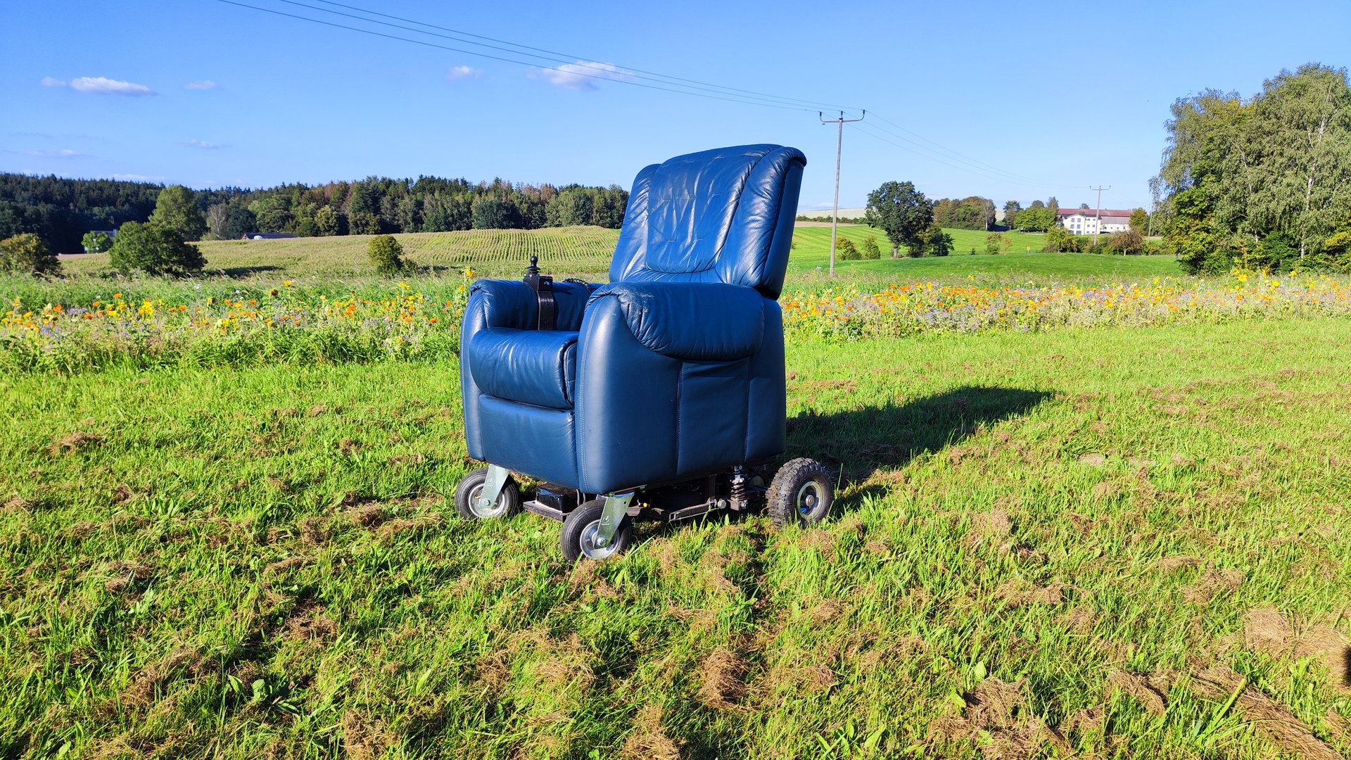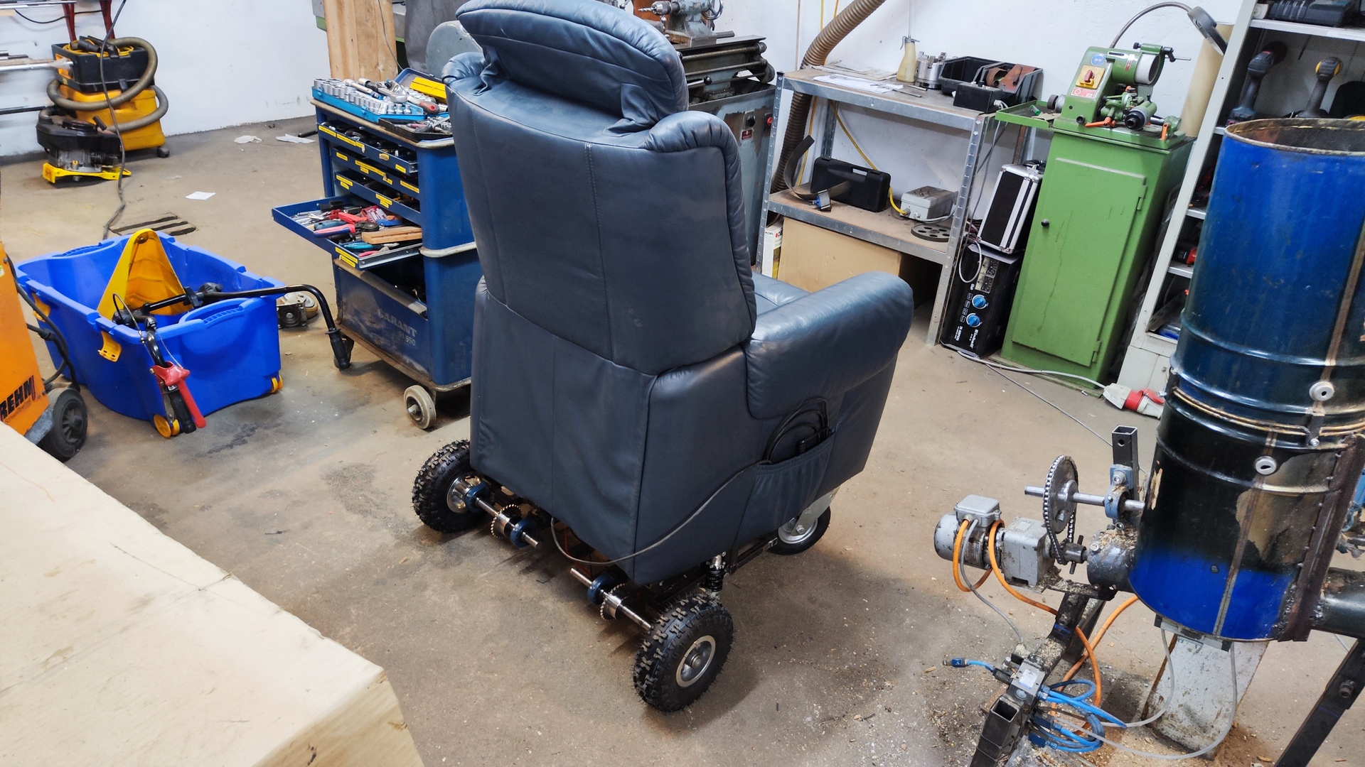
Improved version of the previous electric armchair, featuring electric motors and suspension.
What’s new in V2
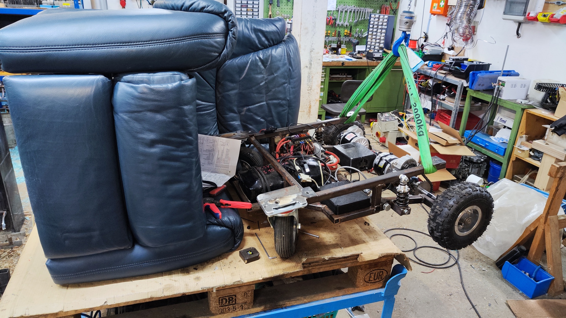
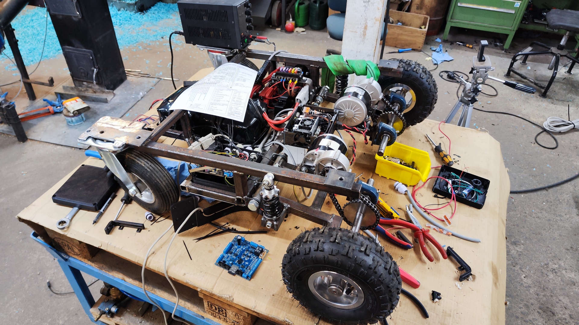
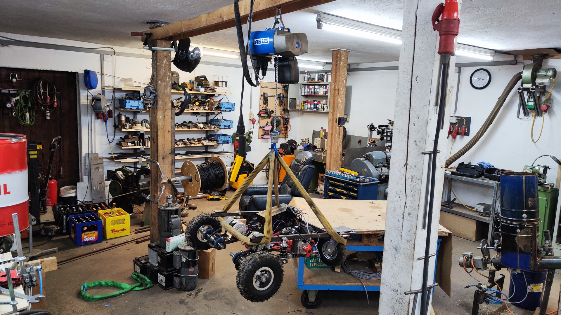
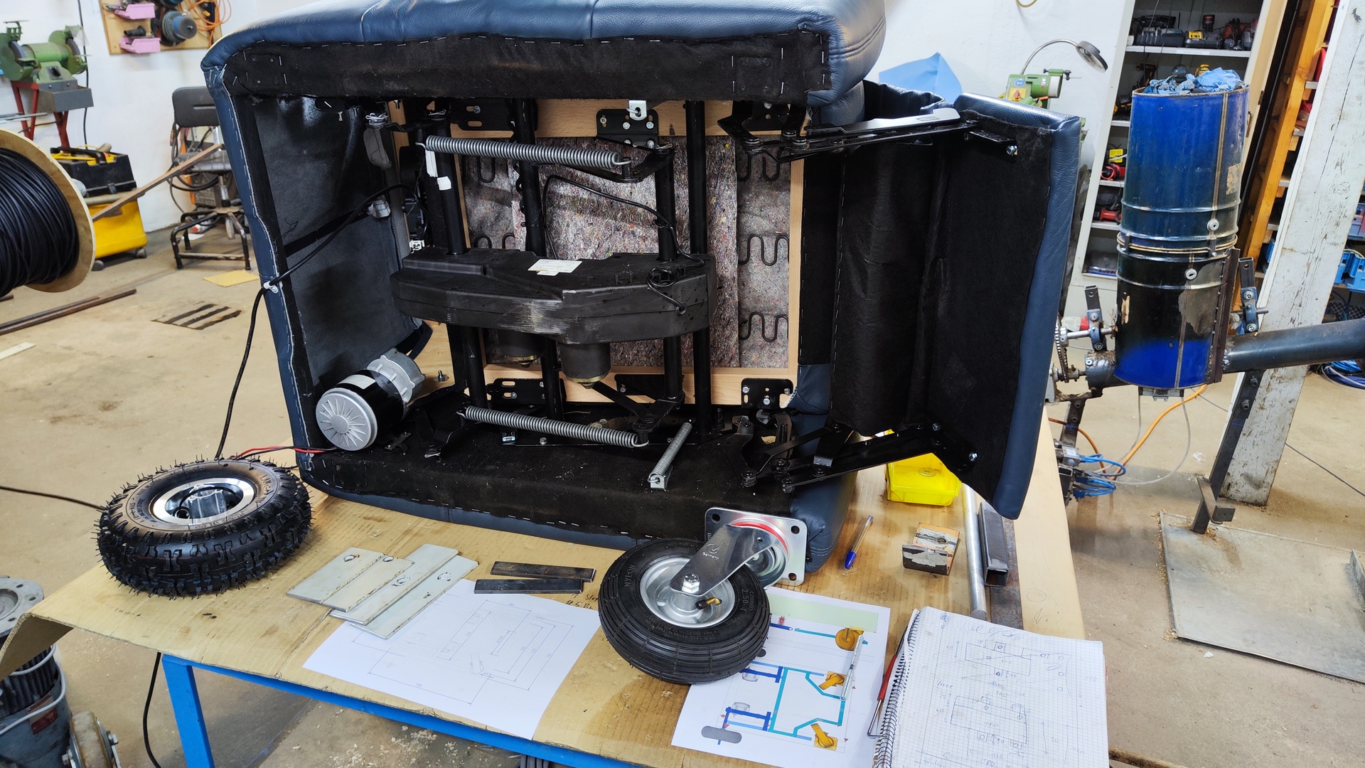
This is a complete rebuild of the first armchair.
The main enhancements in this version are:
- Lithium-ion battery - No more trouble with limited charge cycle durability of lead-acid batteries.
- Suspension - Way better traction and smoother ride.
- Electric chair adjustment - Seating position can be adjusted effortlessly.
- Overall larger - More comfort with a larger armchair.
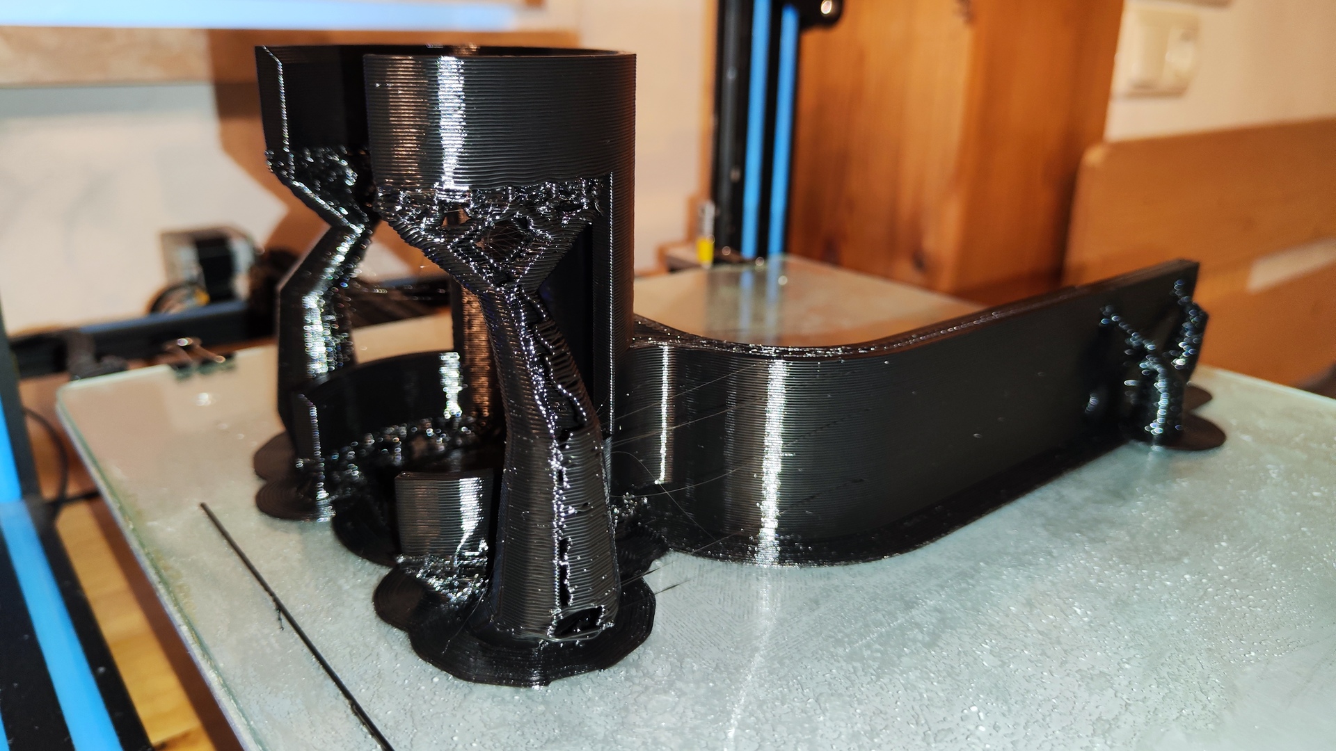
- Easy detachment - Armchair can be removed from the frame quickly for further upgrades
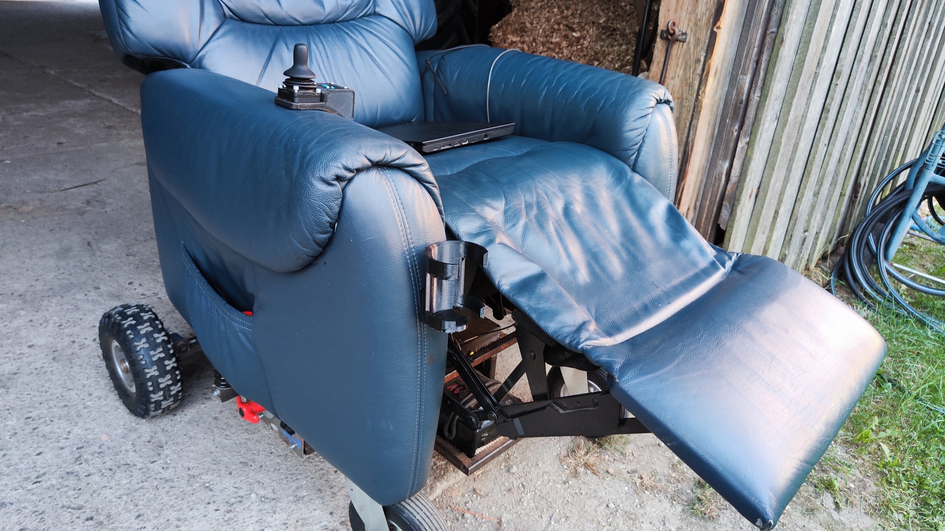
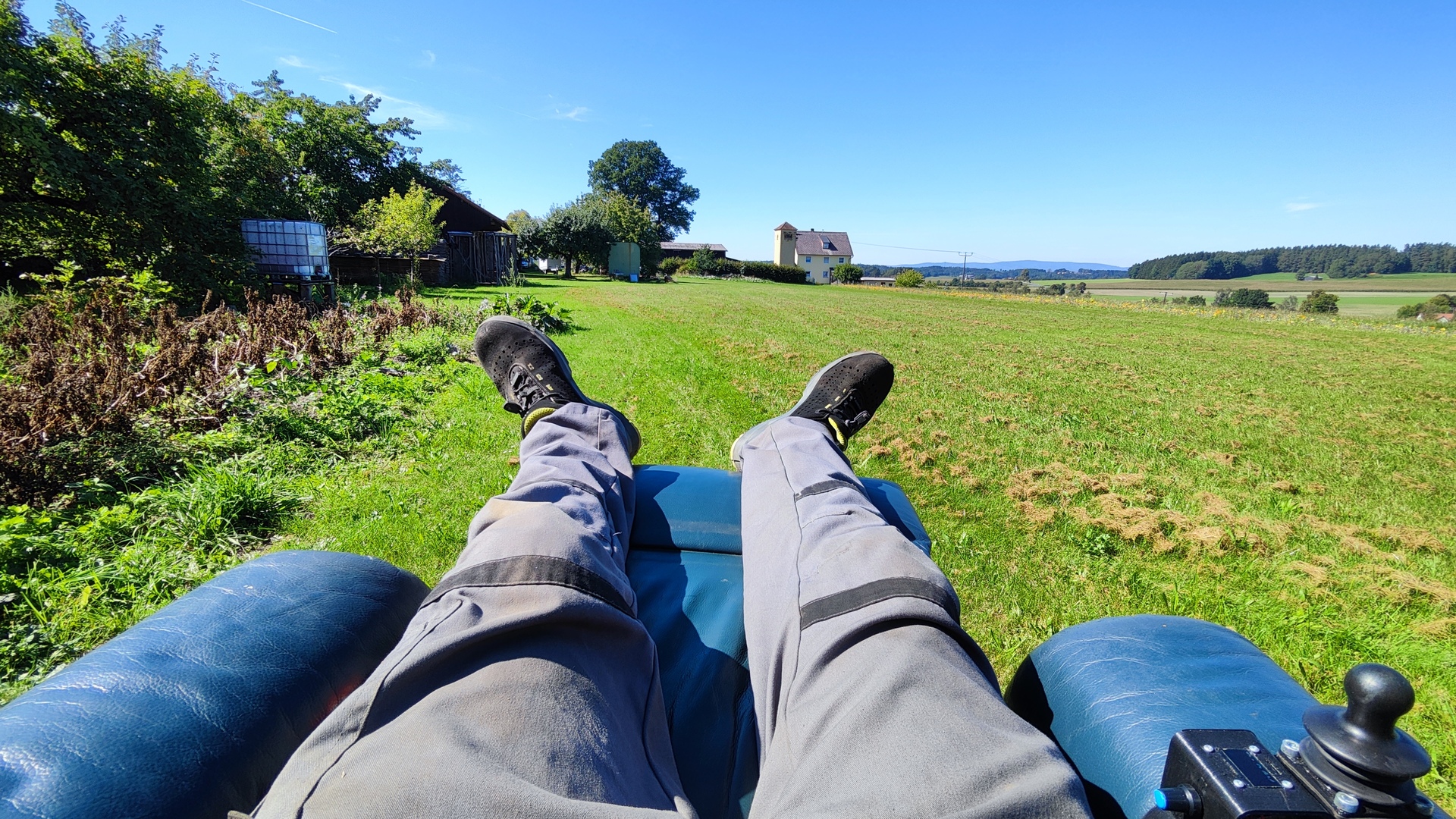
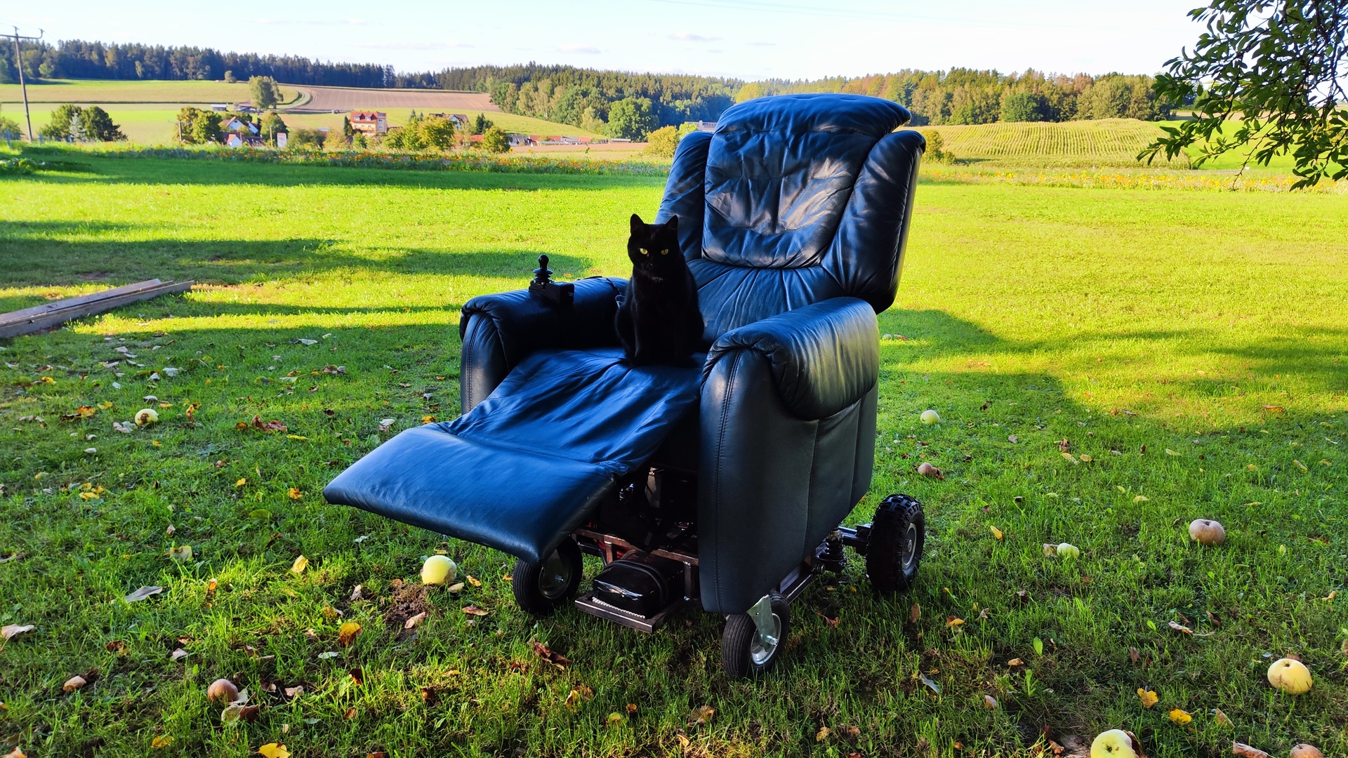
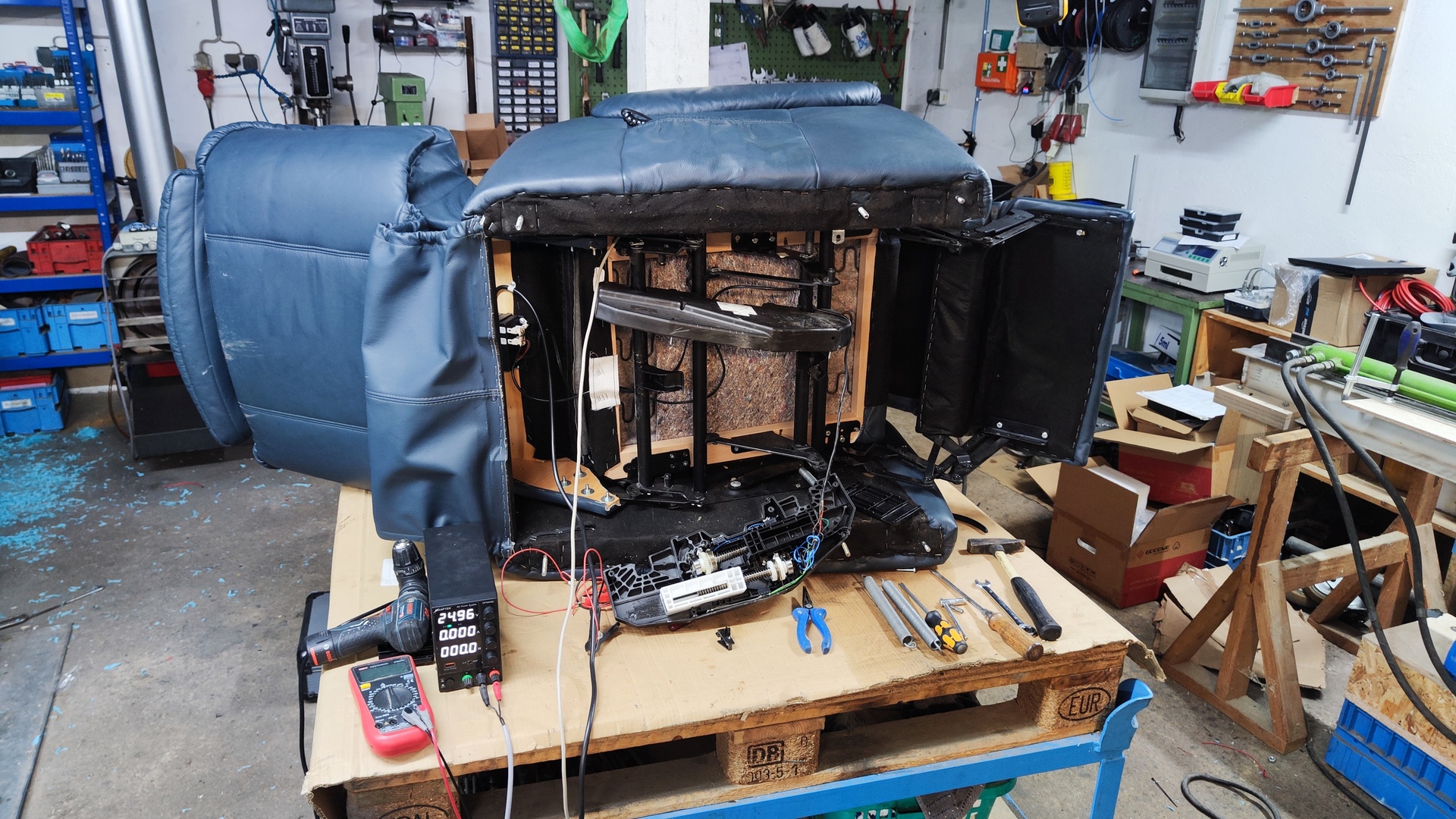
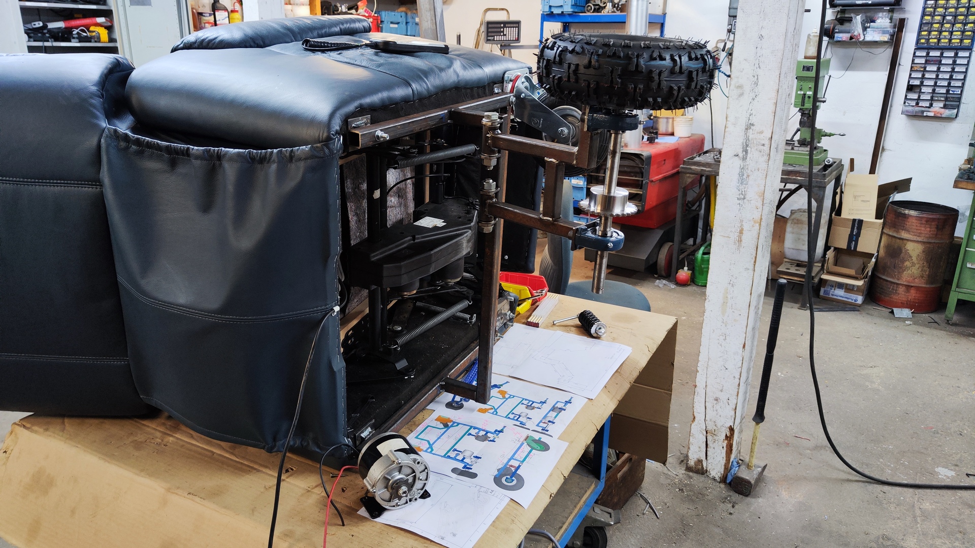
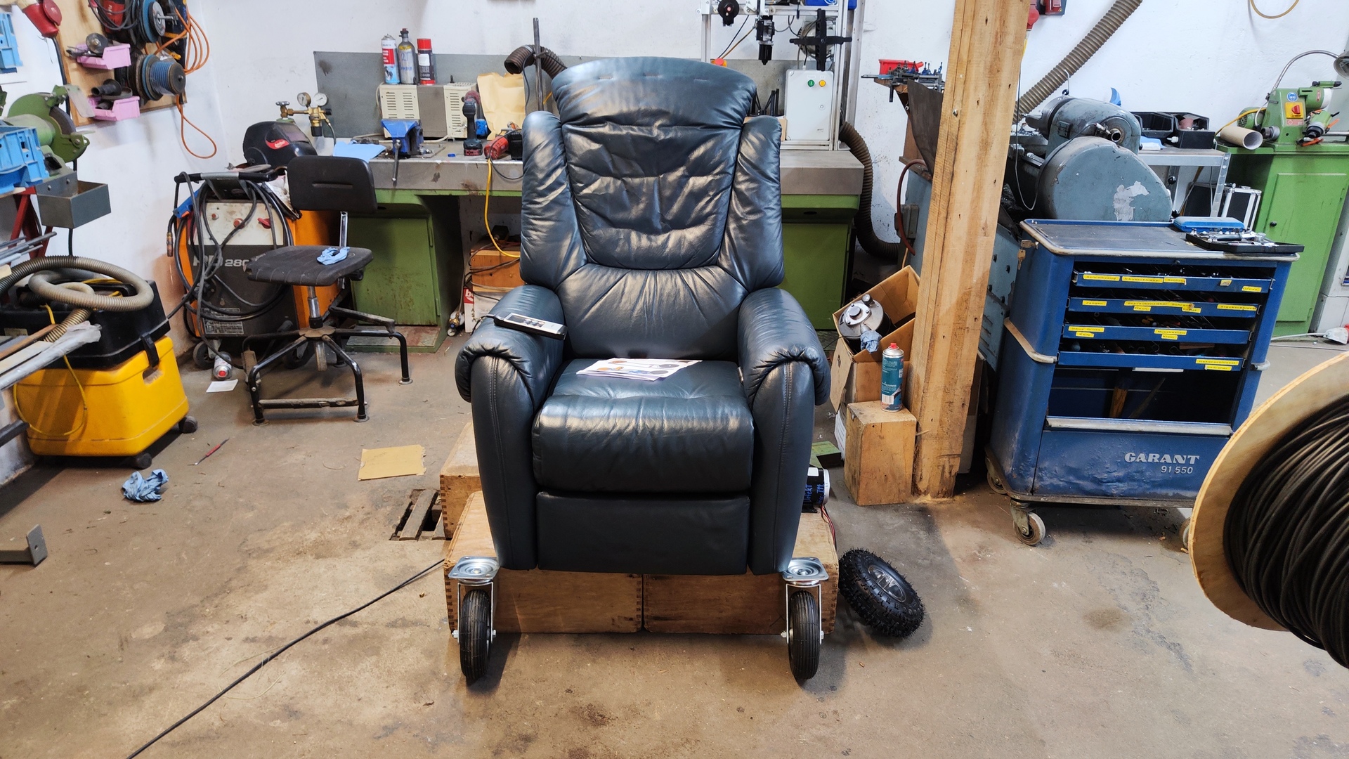
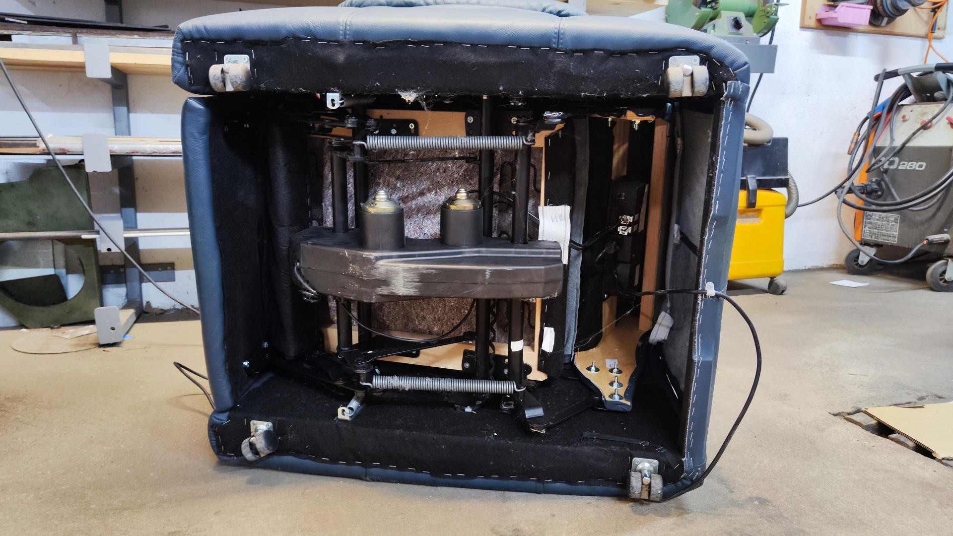
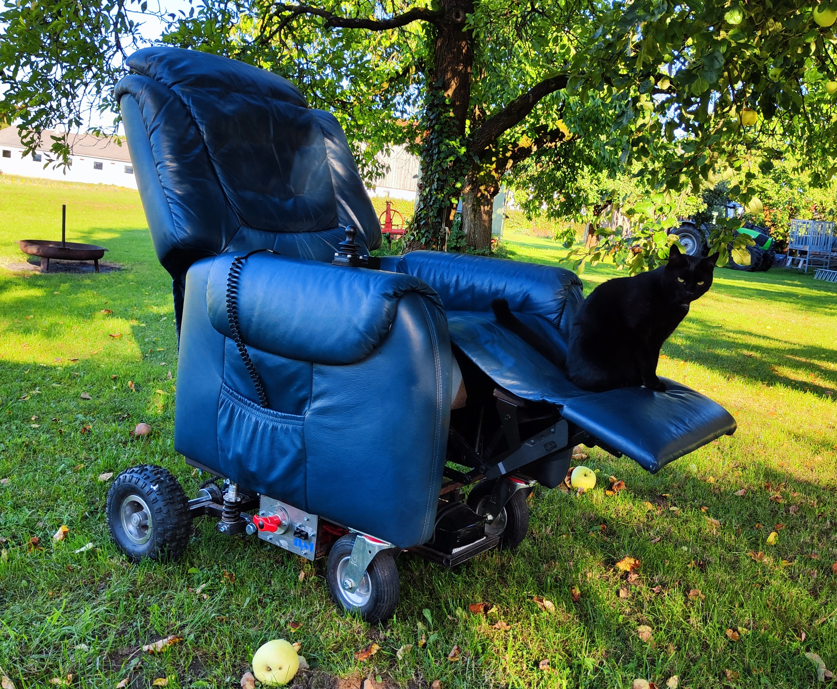
 New armchair in flat position
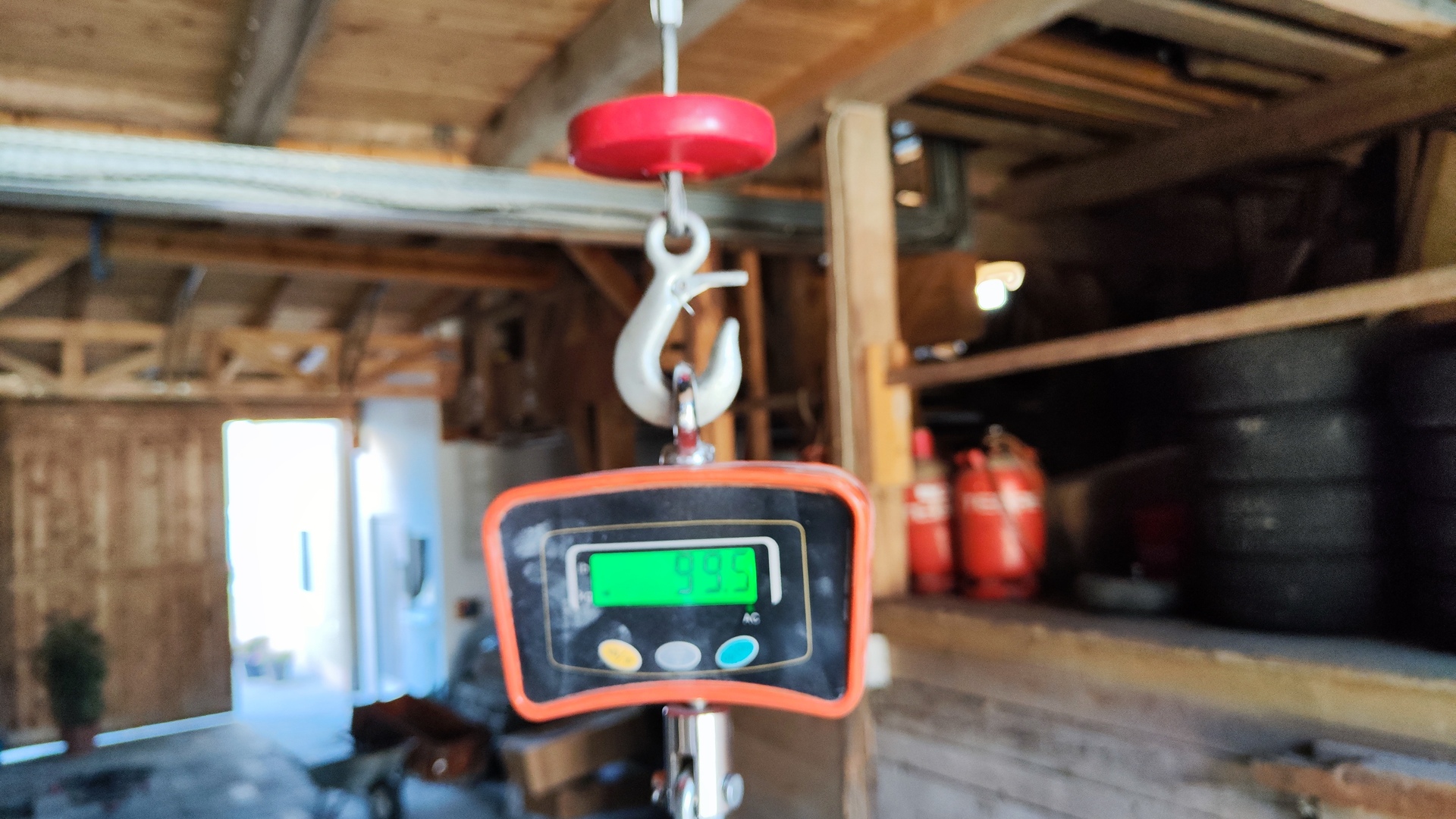
Specification
- Top-speed: 9 km/h
- Range: Approx 1 hour
- Turning radius: 0.4 m
-
Weight: 99.5 kg
-
Current Features:
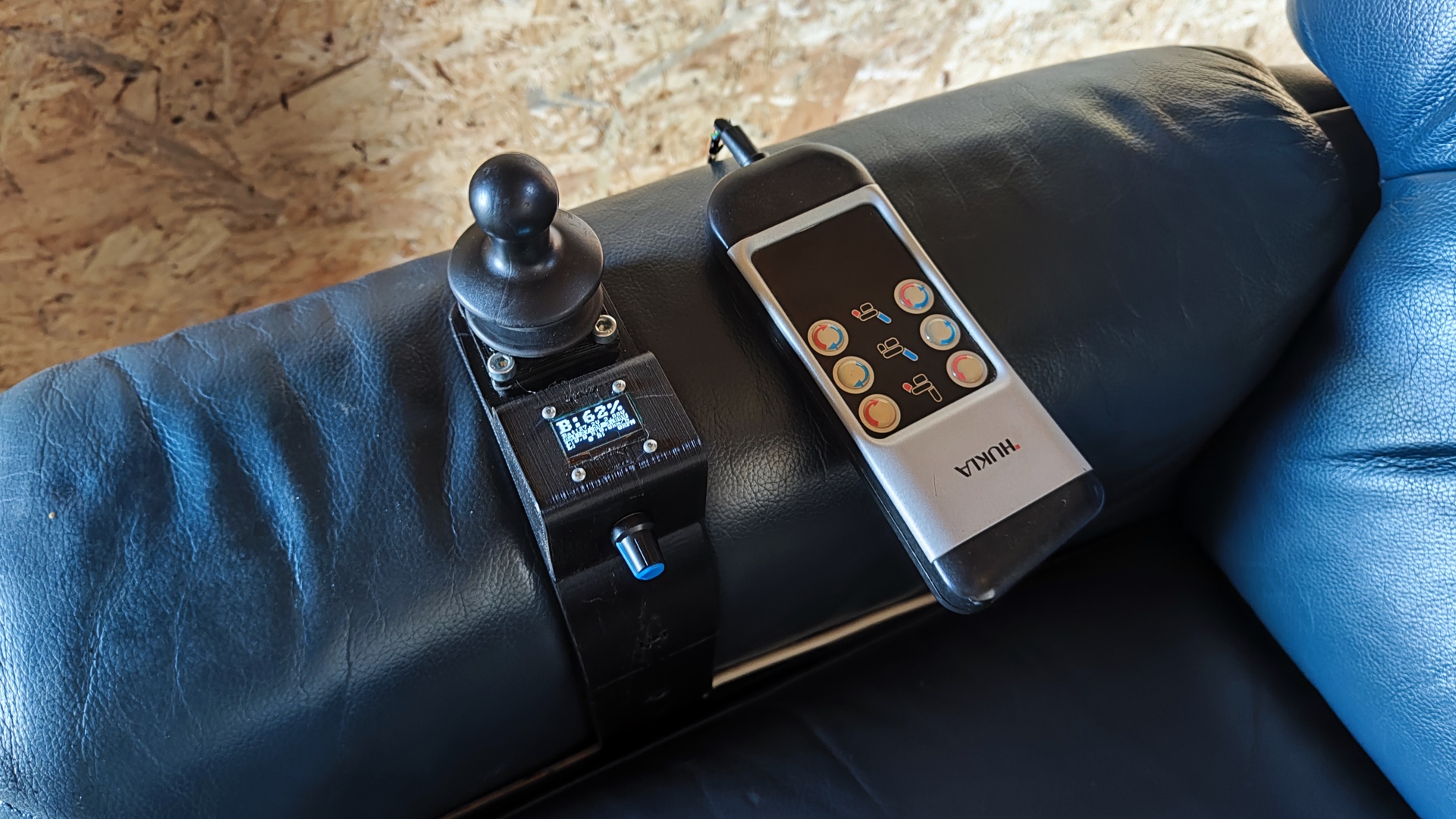
- Individual tire control
- Joystick operation
- Remote control via WiFi
- Electric seat adjustment
- Massage function
- USB charging port
- OLED display
-
Future Features (Work in Progress):
- Additional sensors: e.g. Accelerometer, Lidar sensor, GPS receiver
- Anti-slip regulation
- Self-driving algorithm
- Integrated lighting
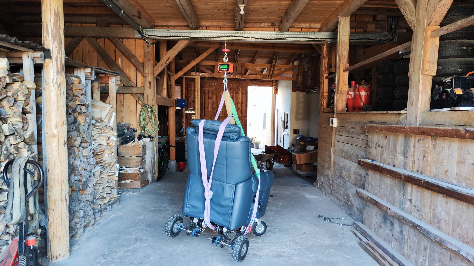
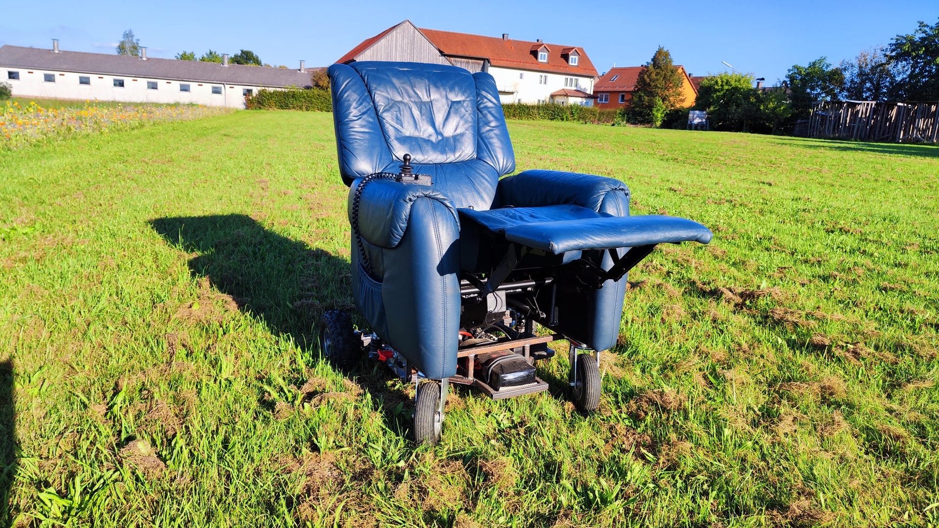
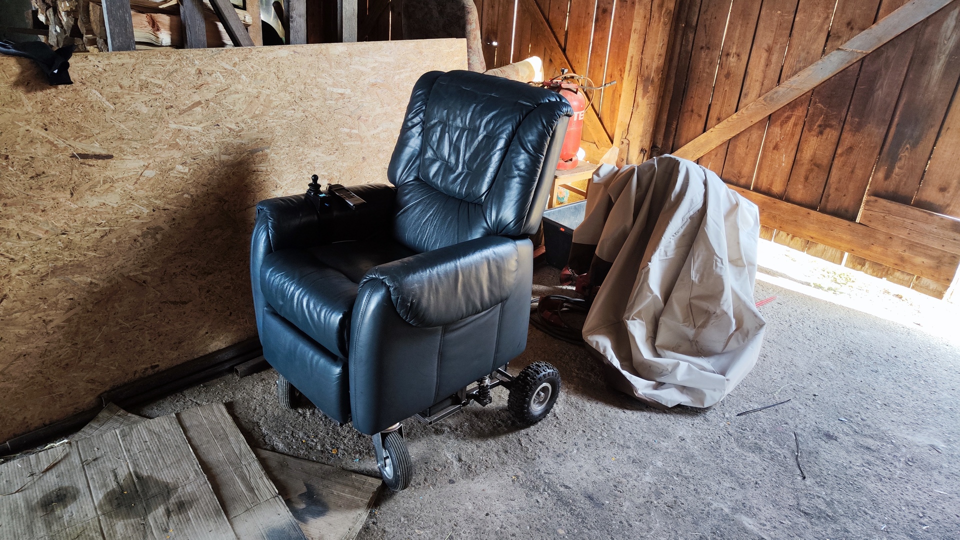
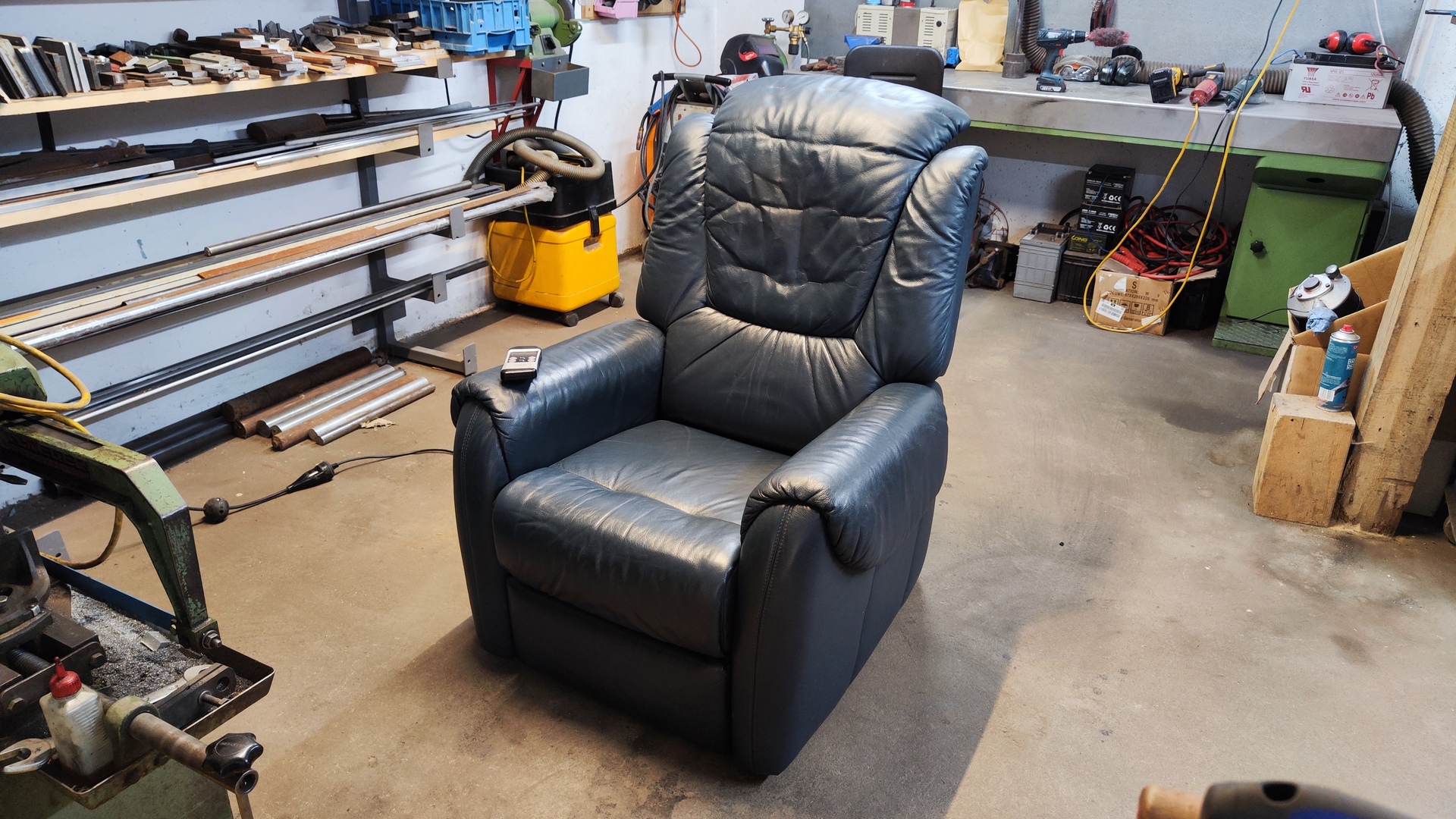
 Parked armchair
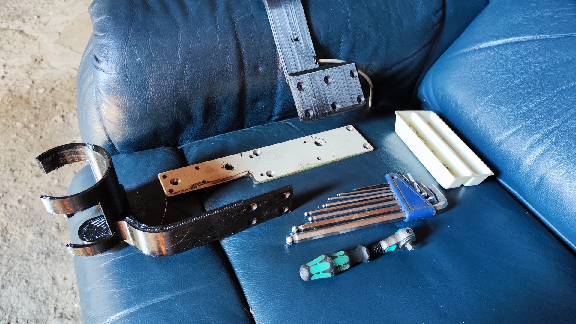
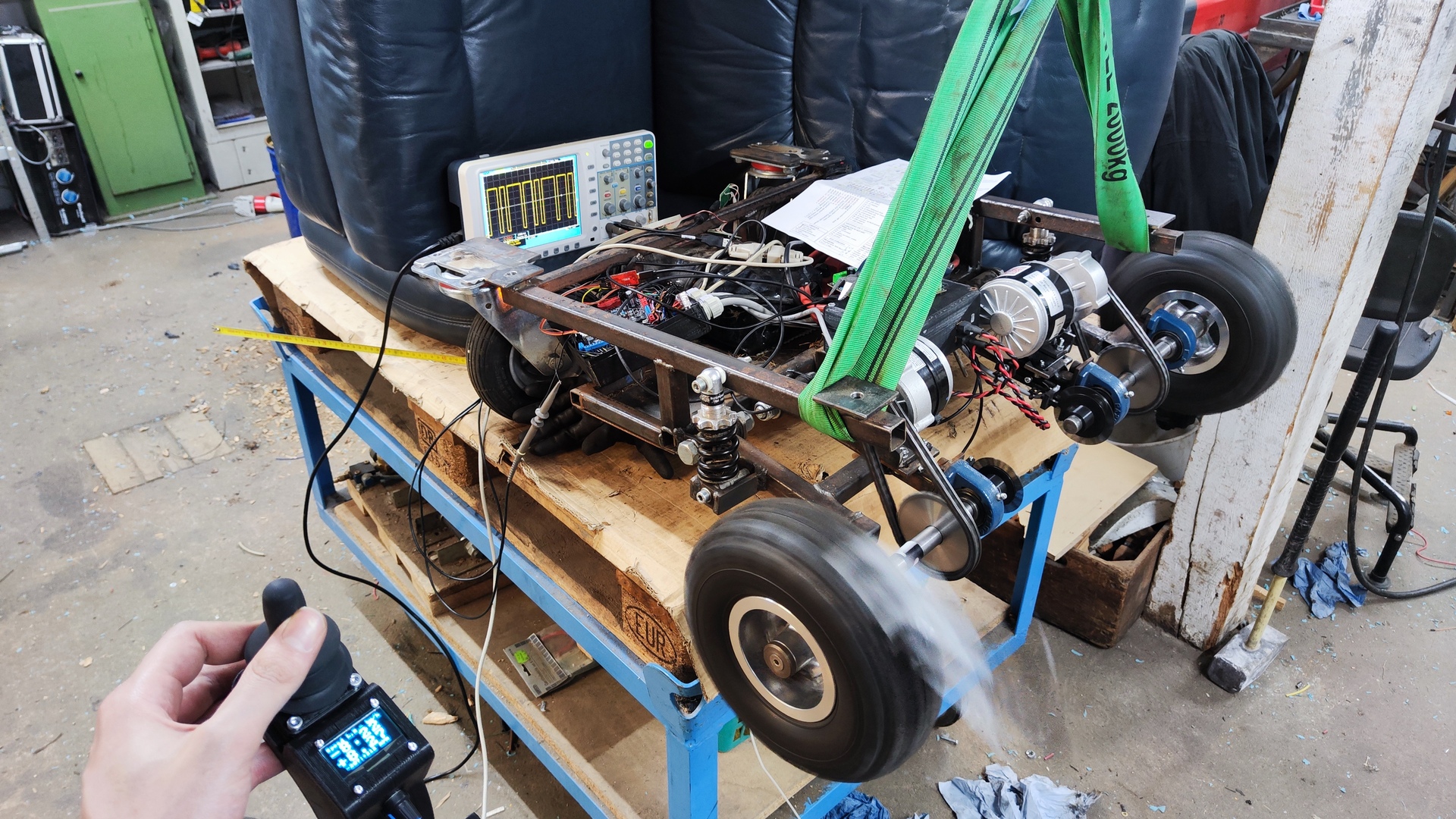
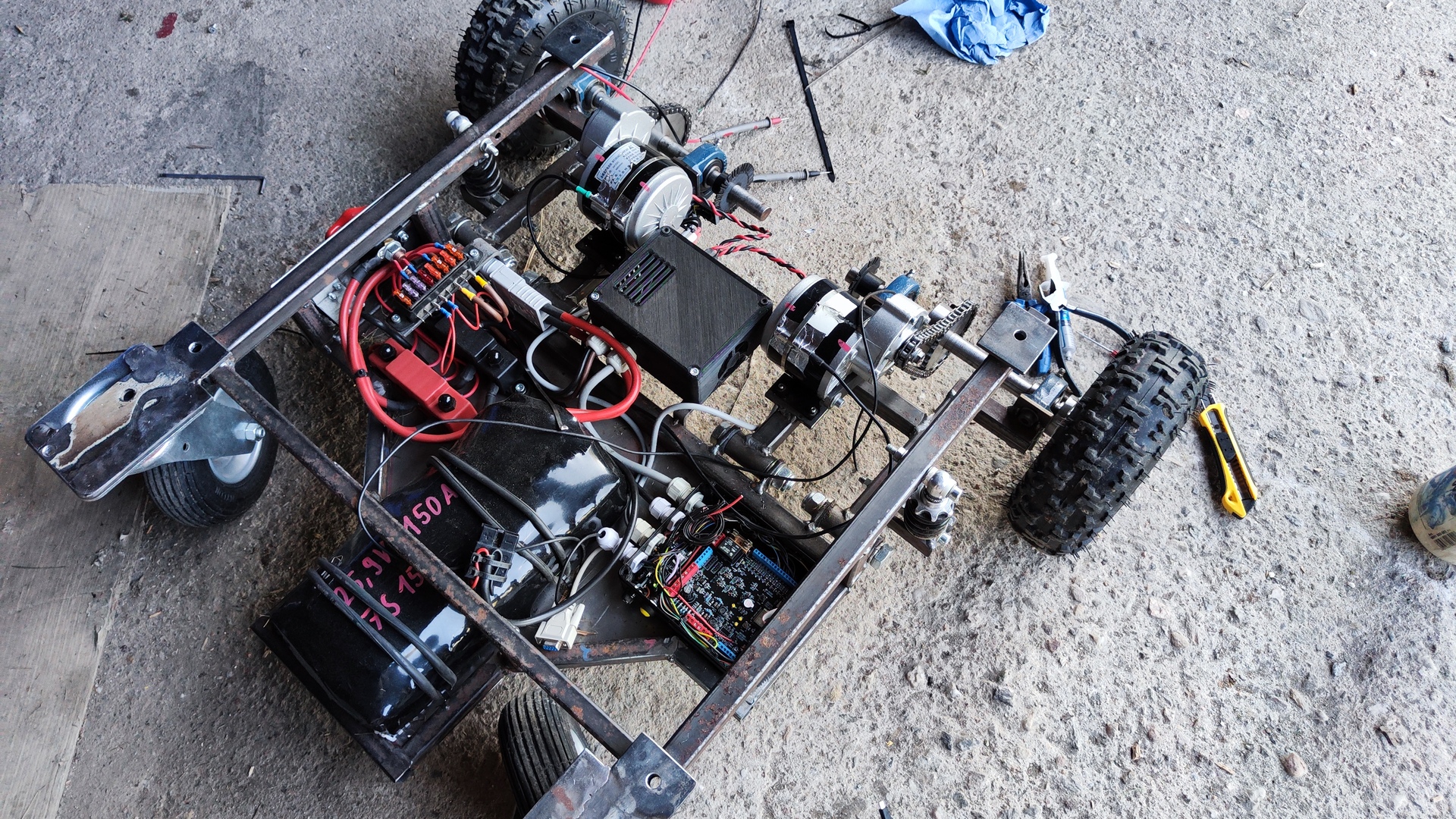
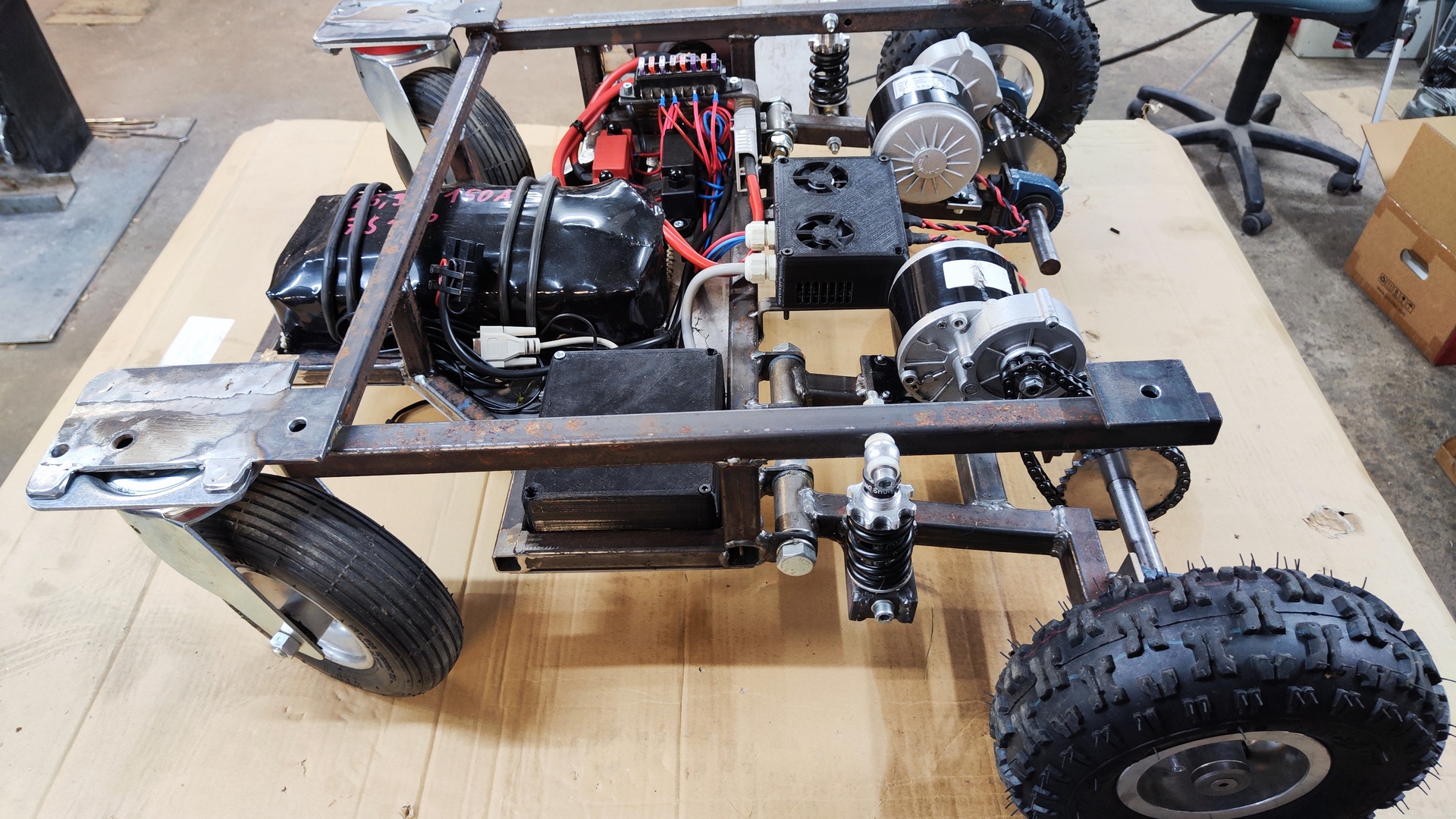
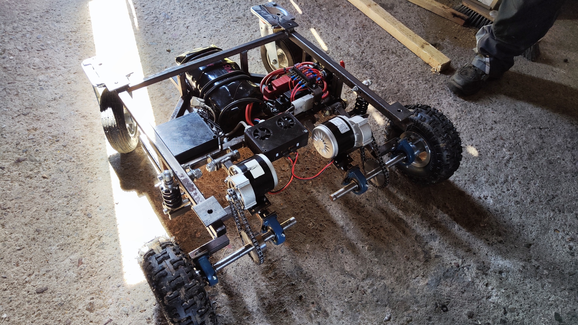
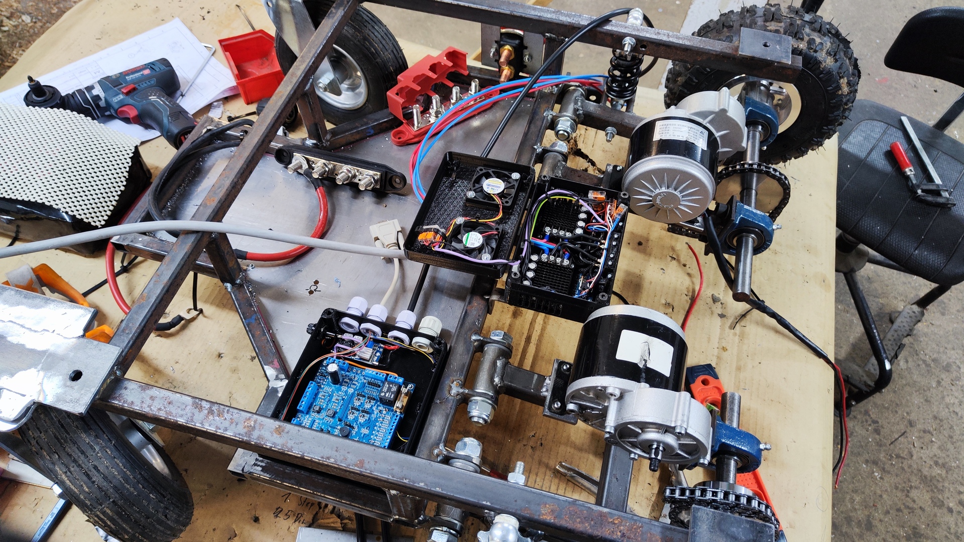
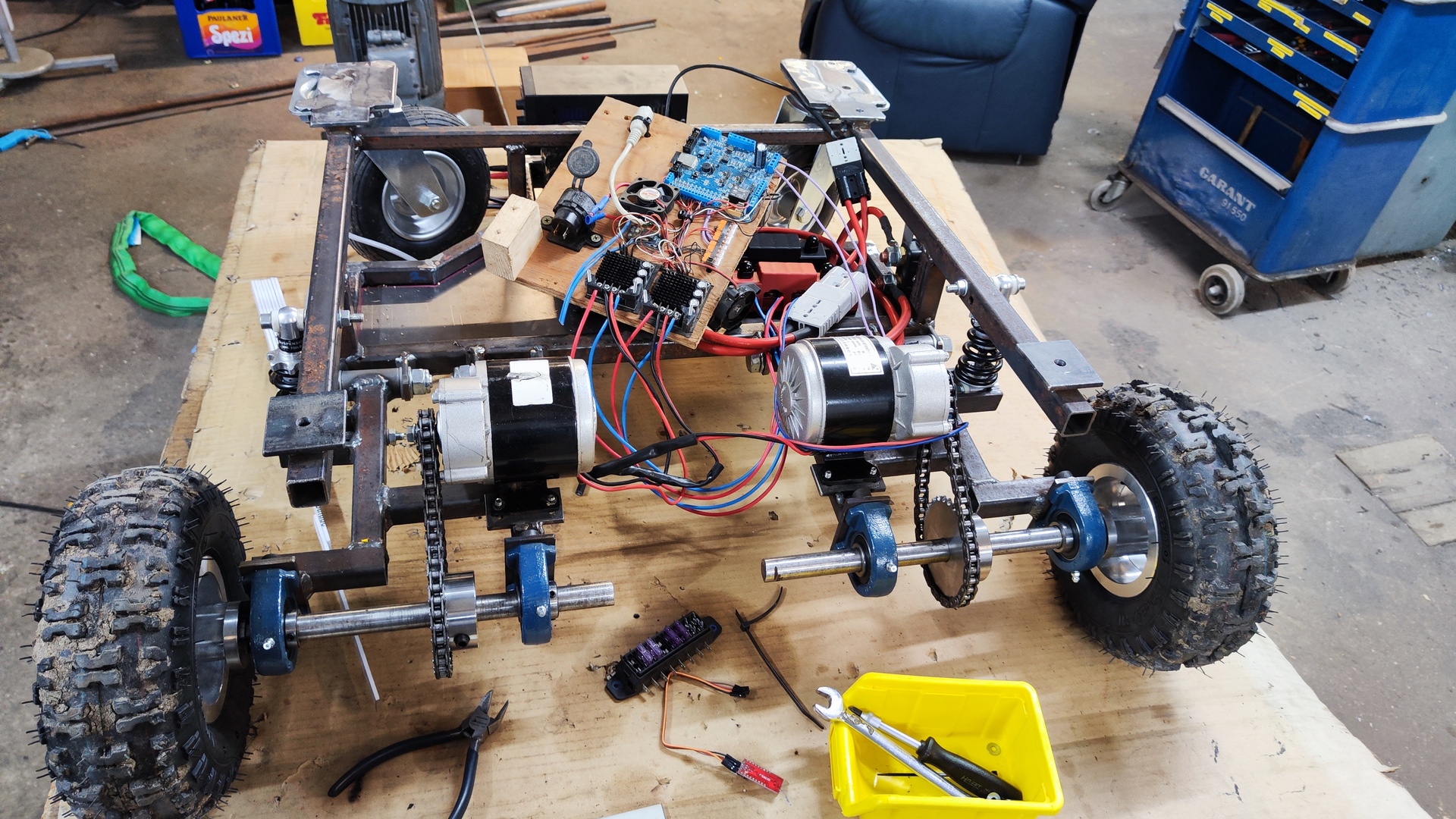
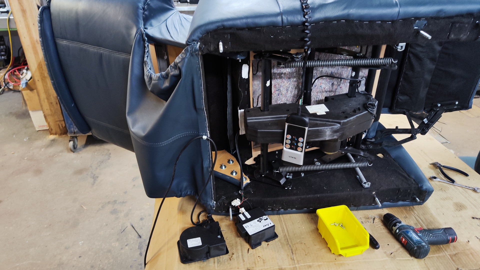
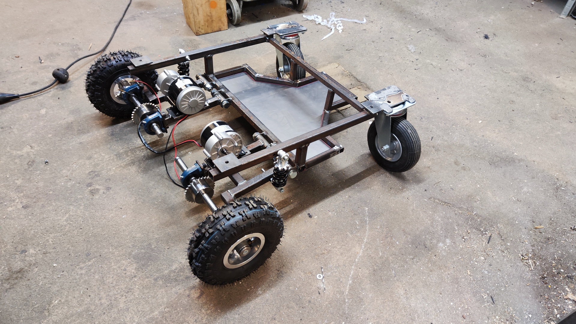
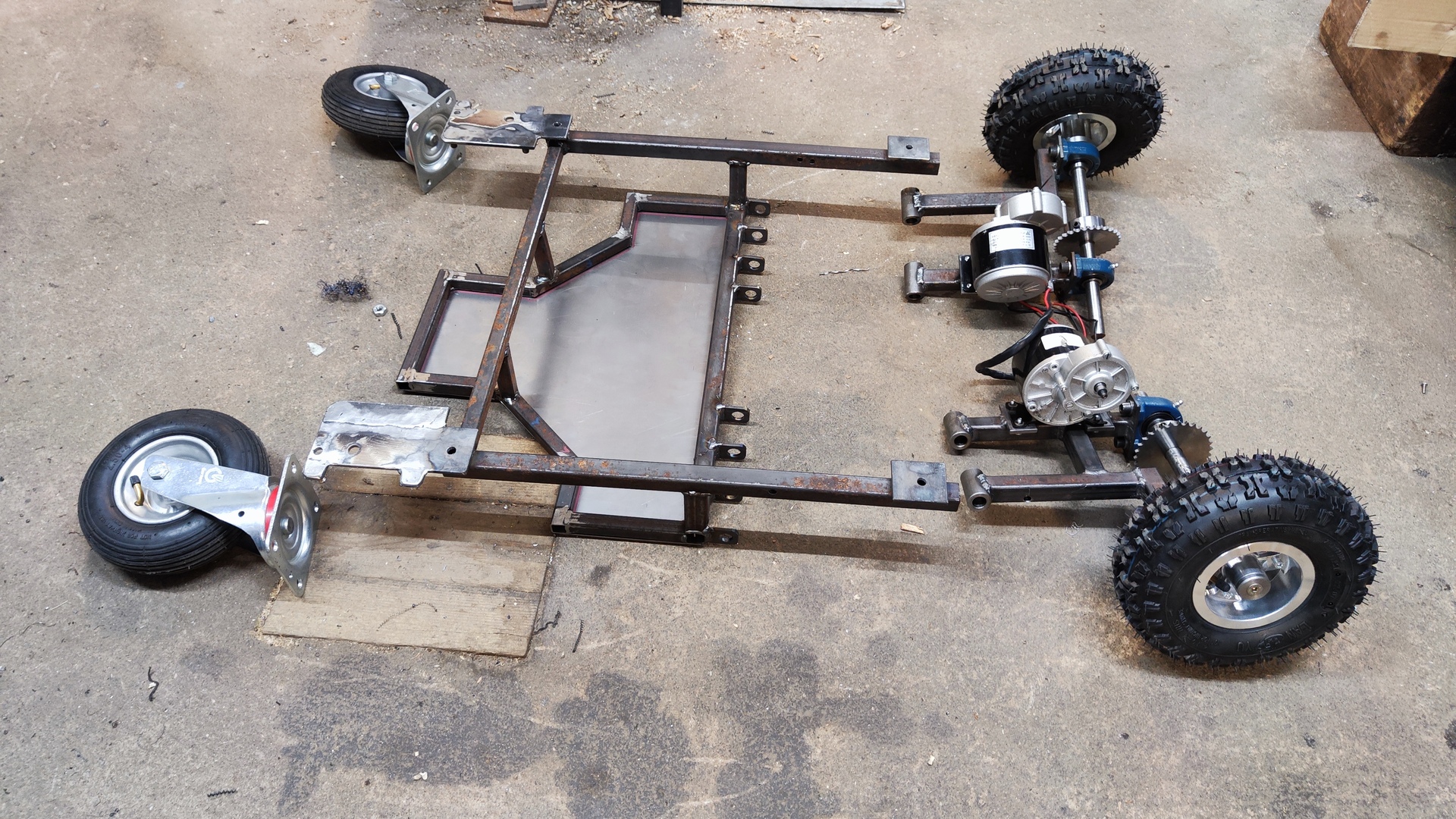
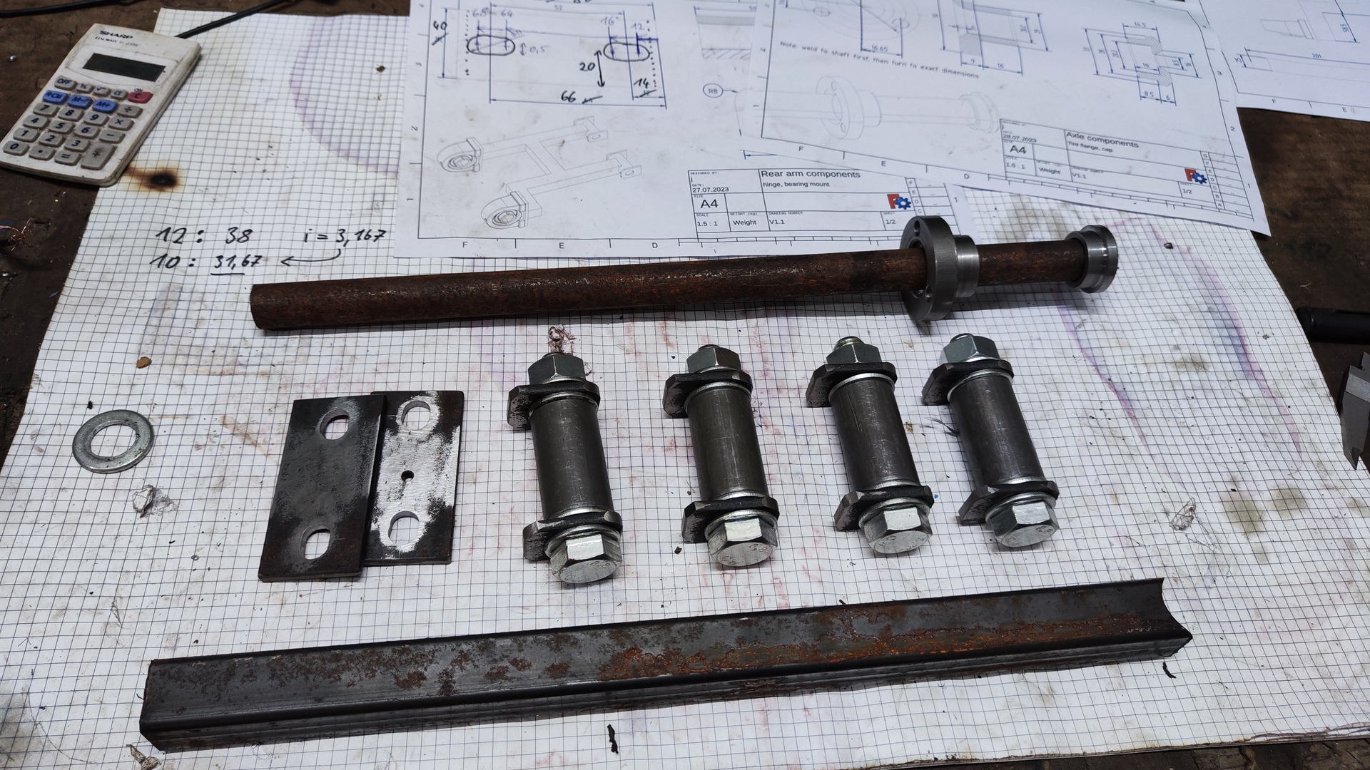
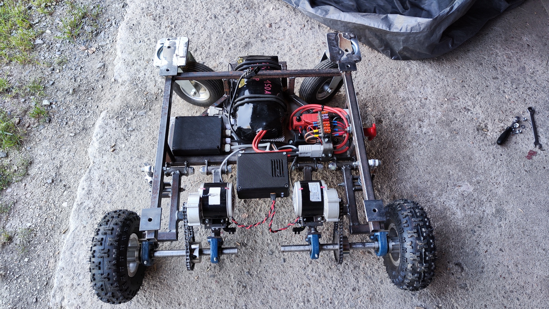
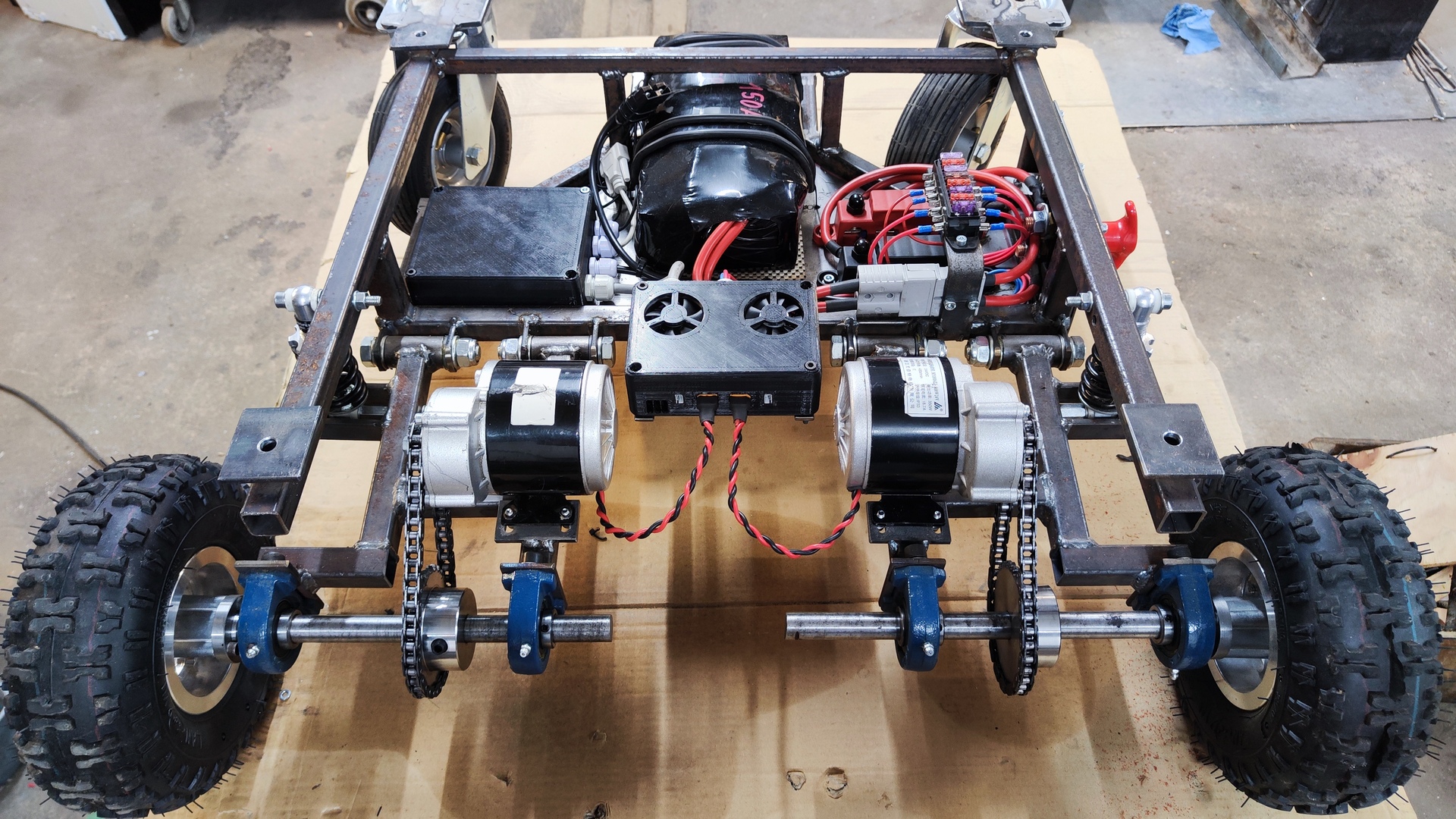
Components
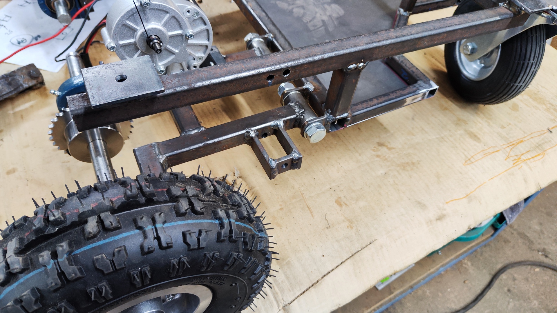
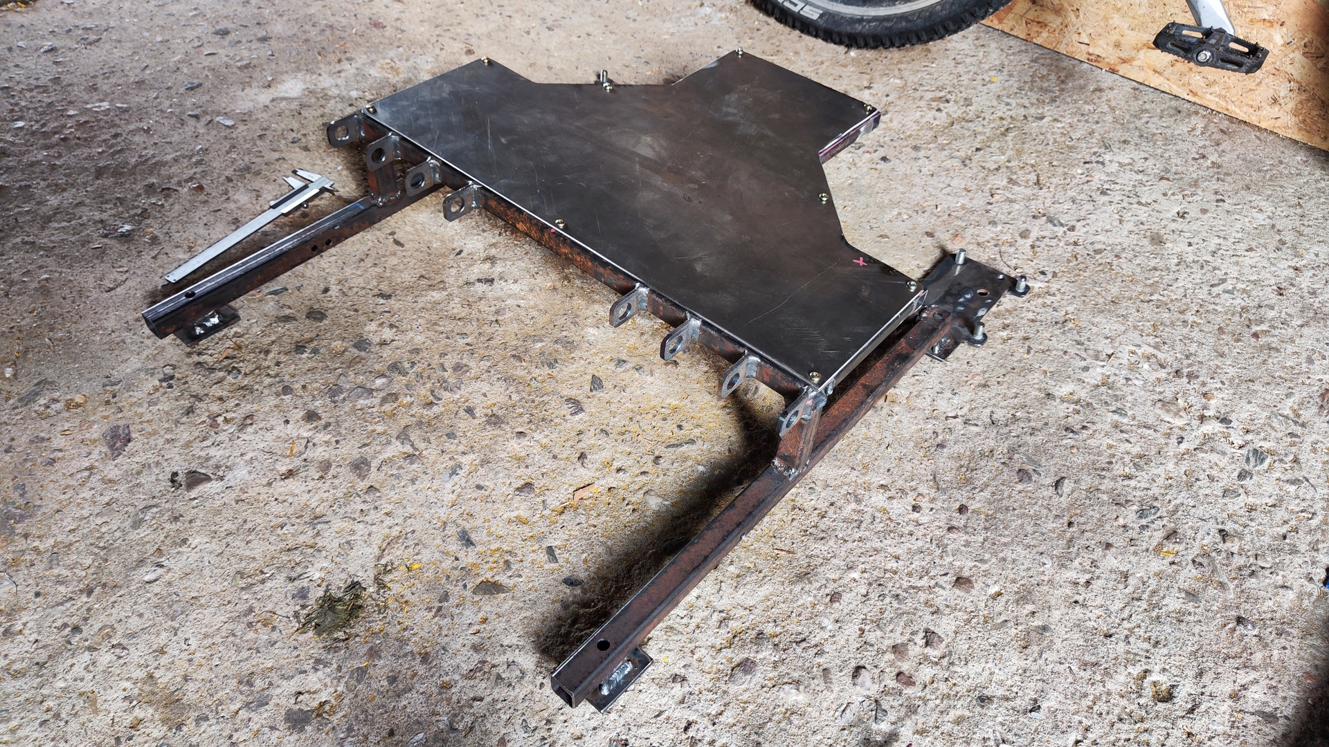
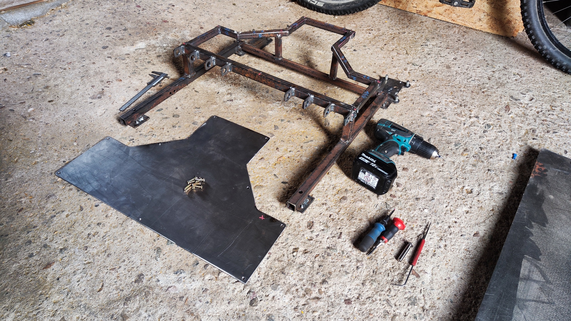
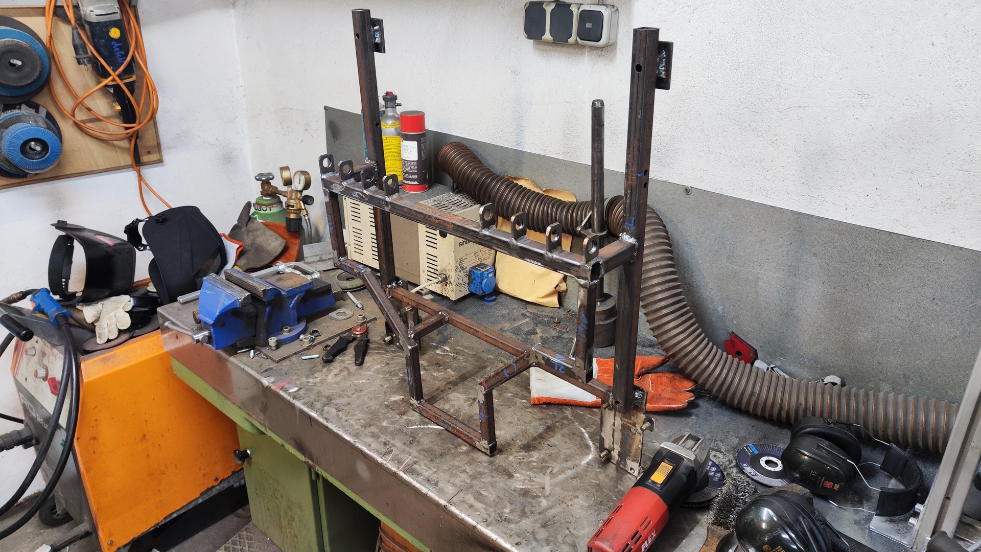
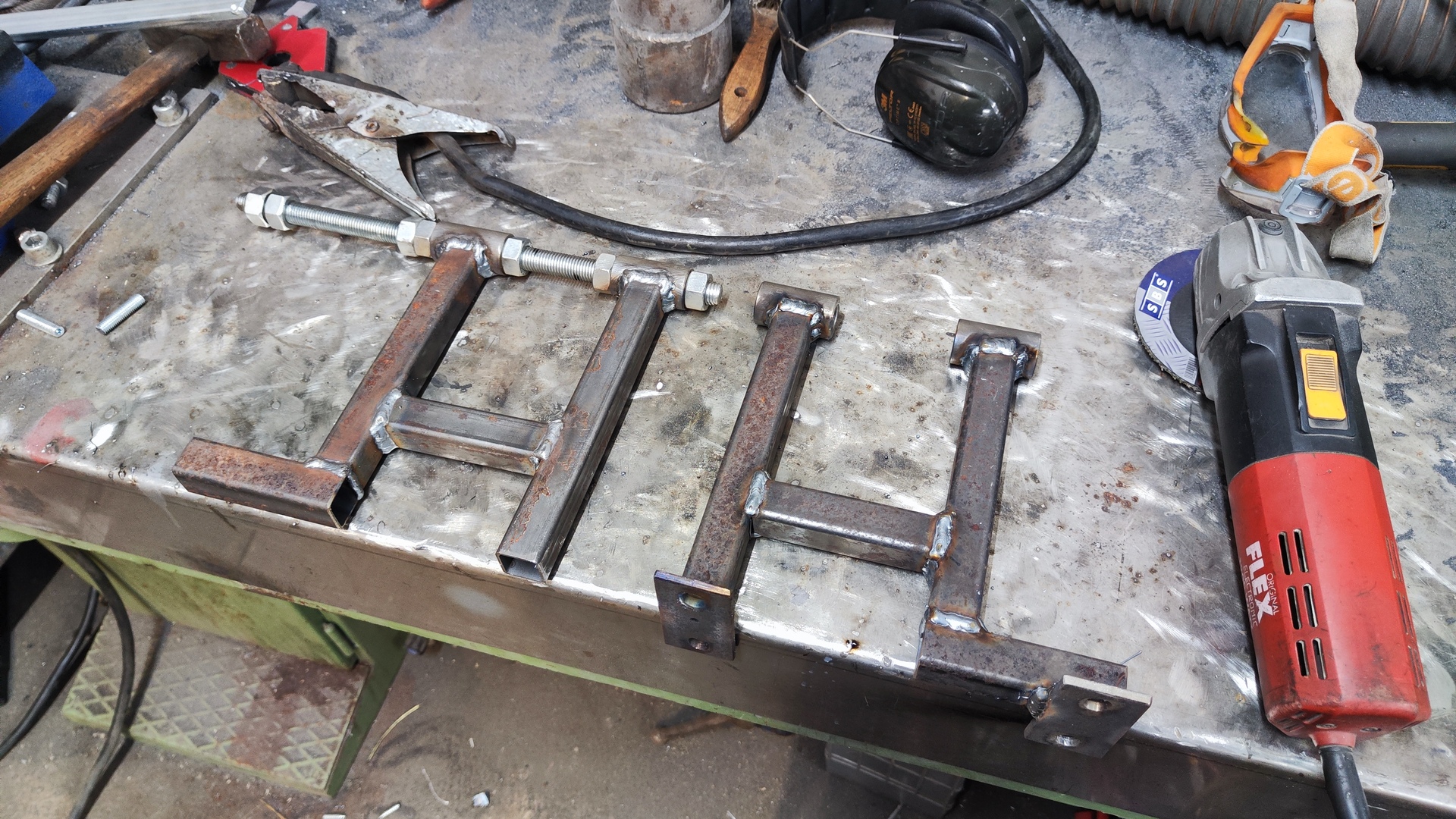
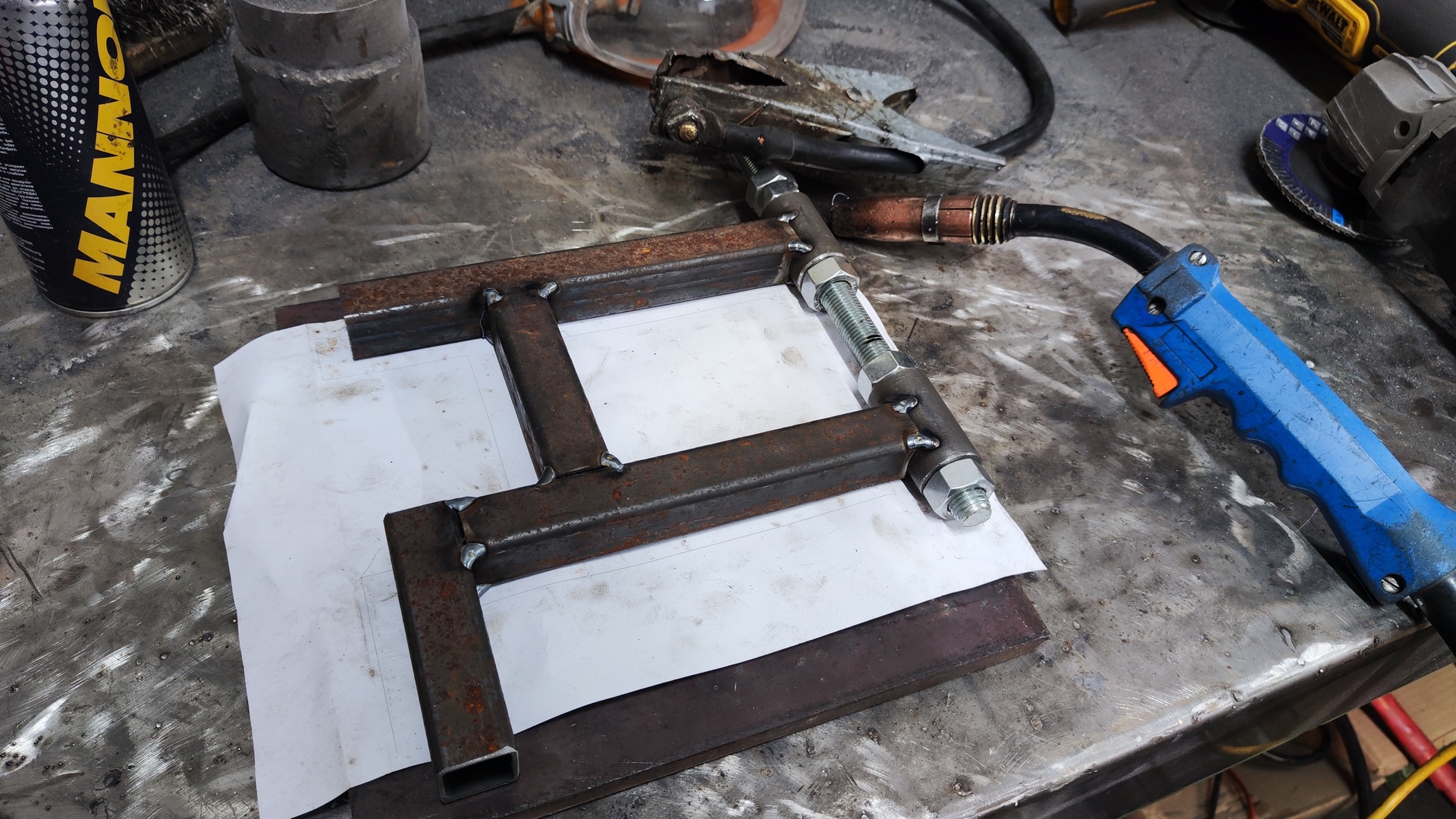
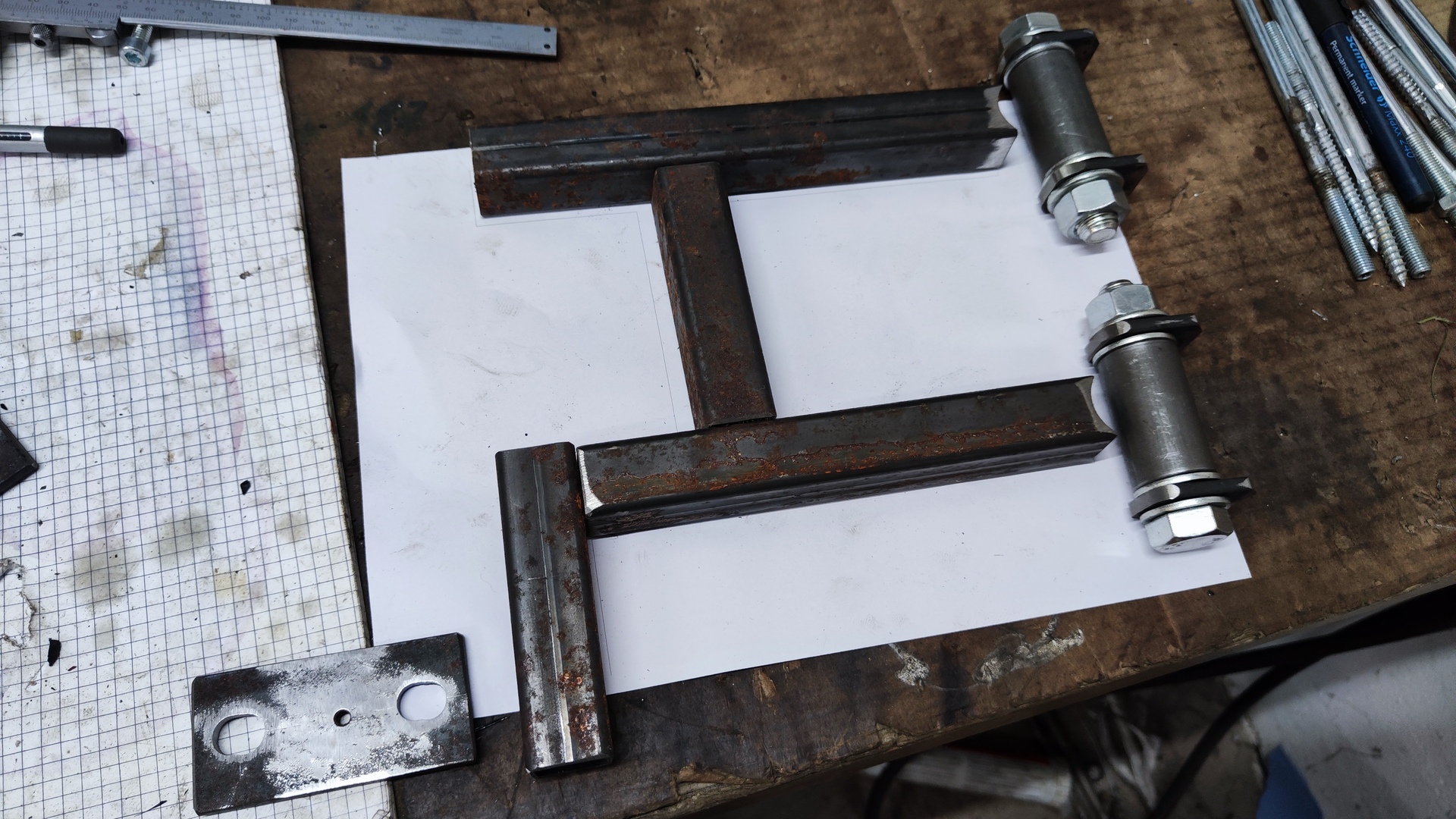
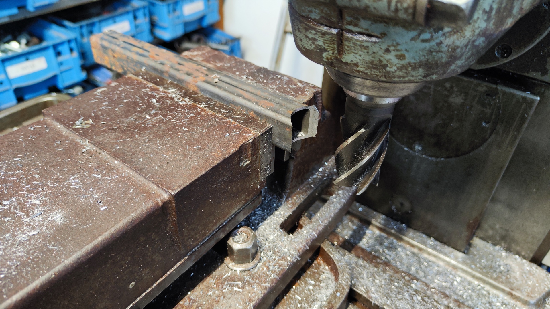
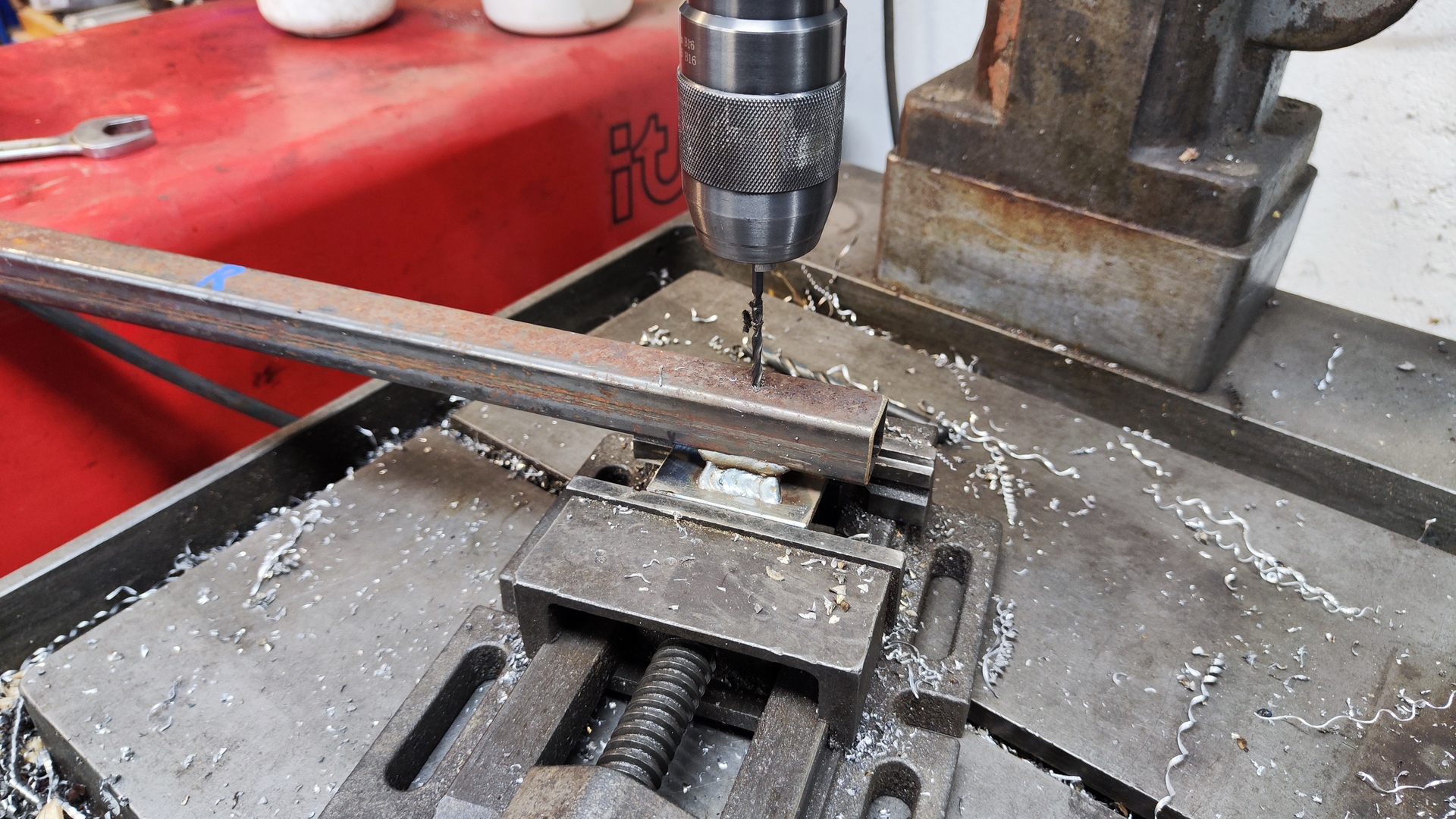
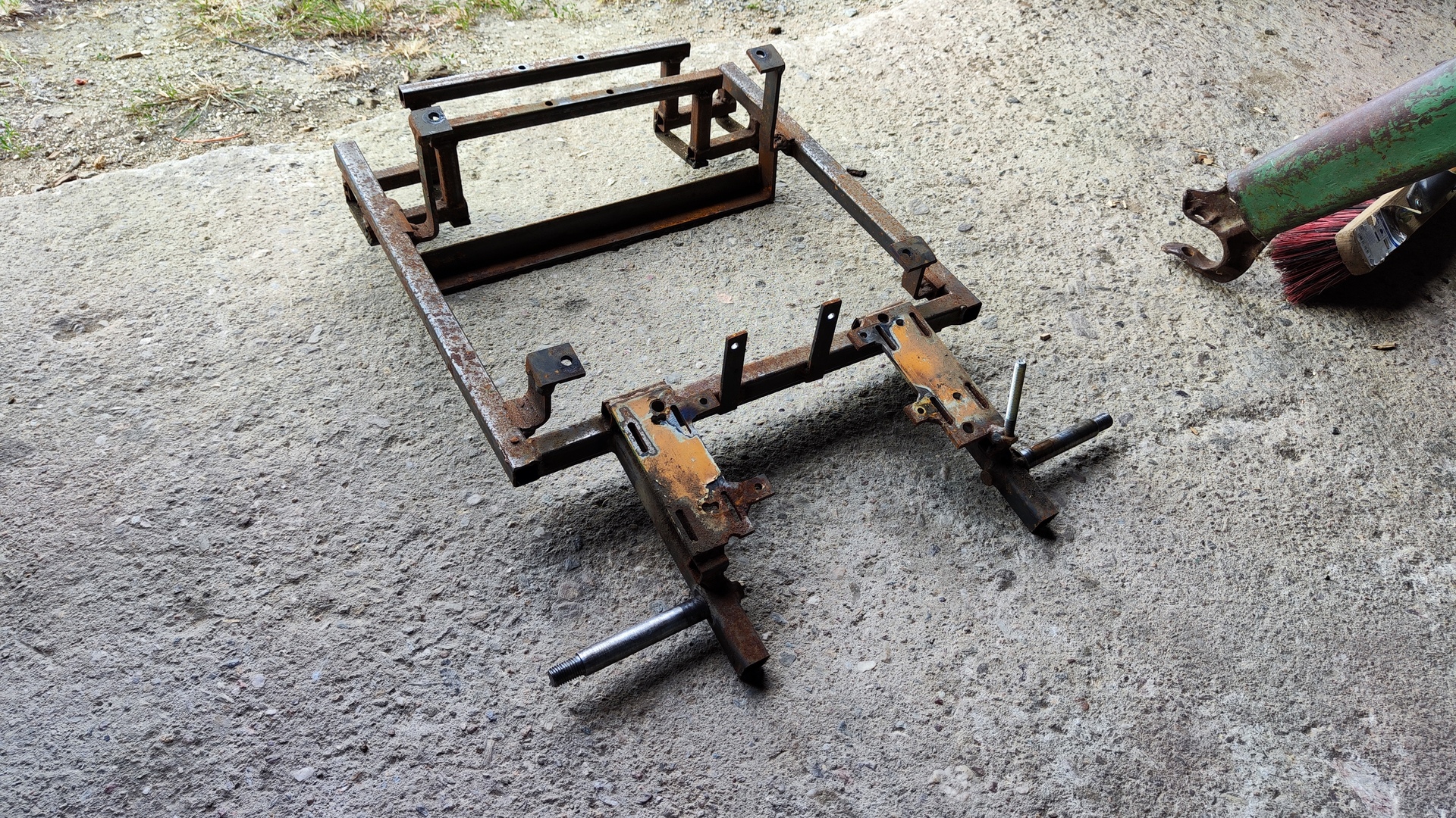
Mechanical
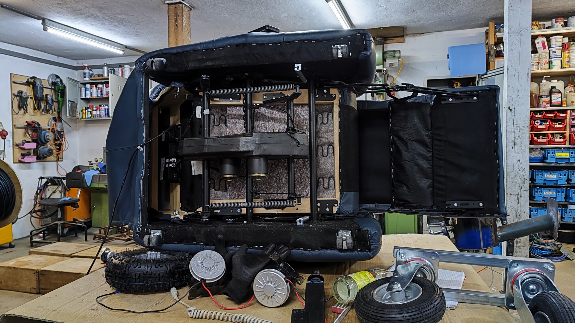
- Armchair: Second-hand
-
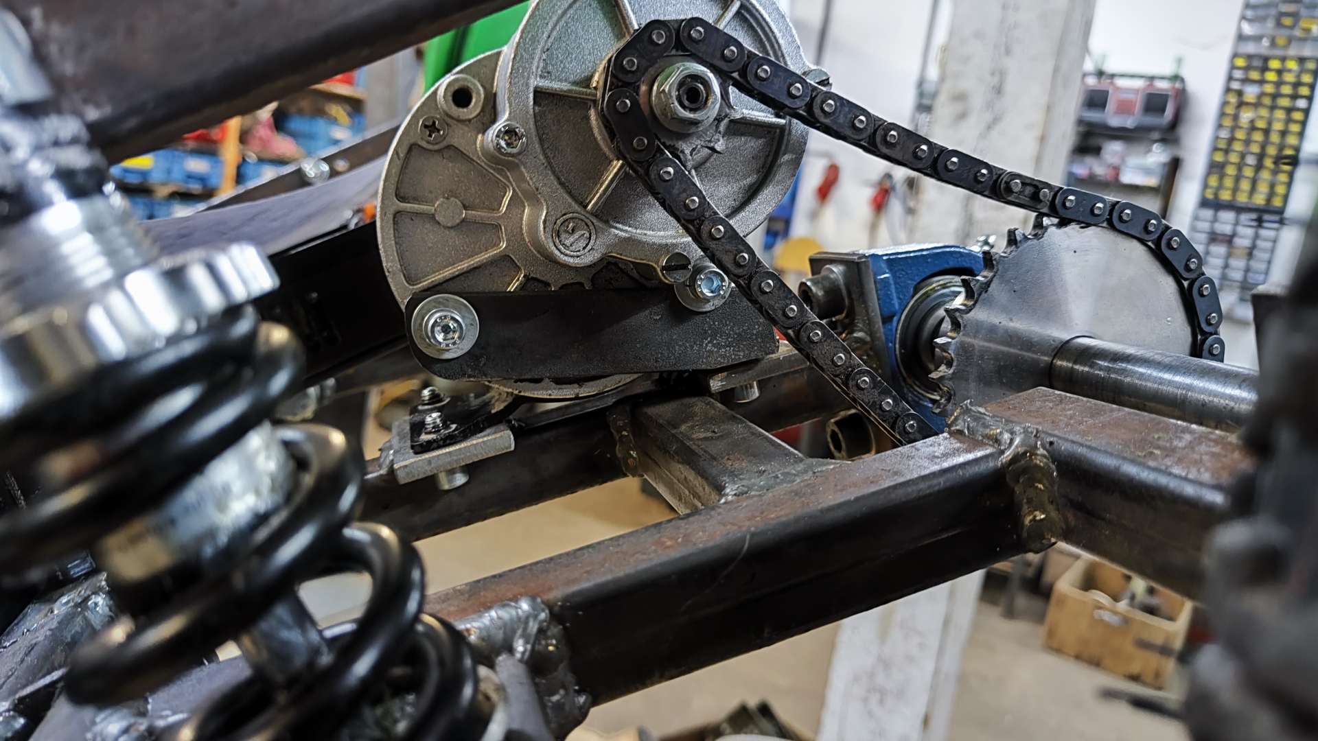
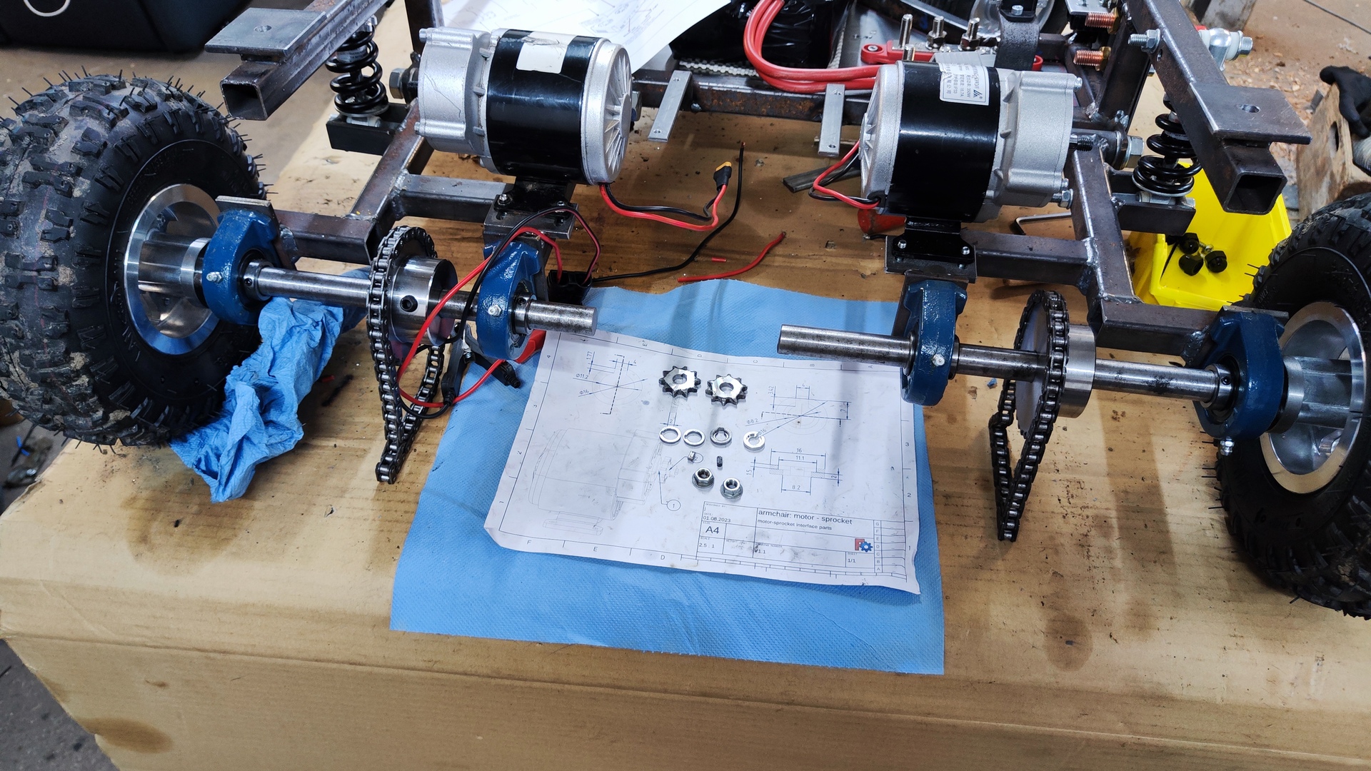
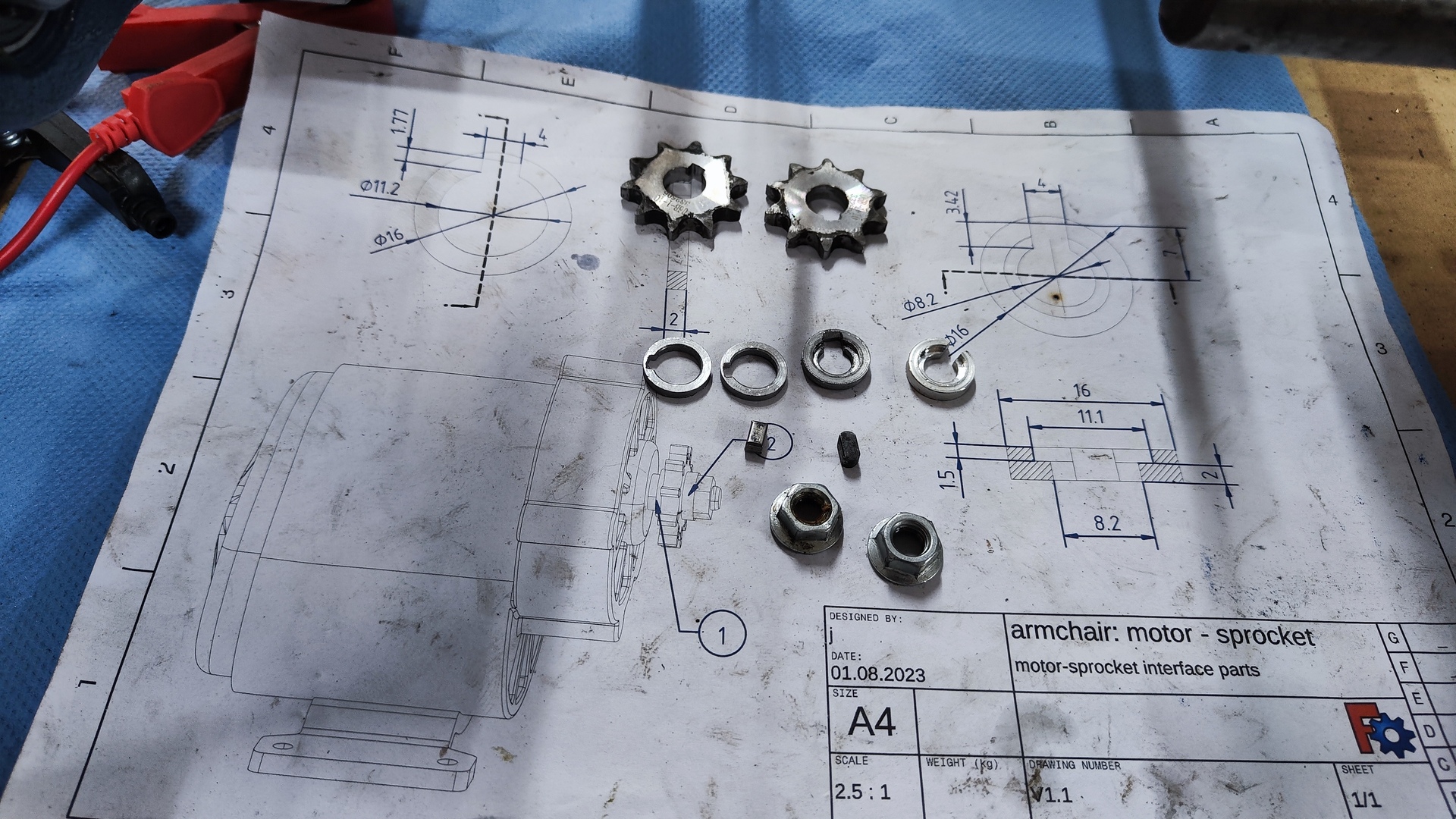
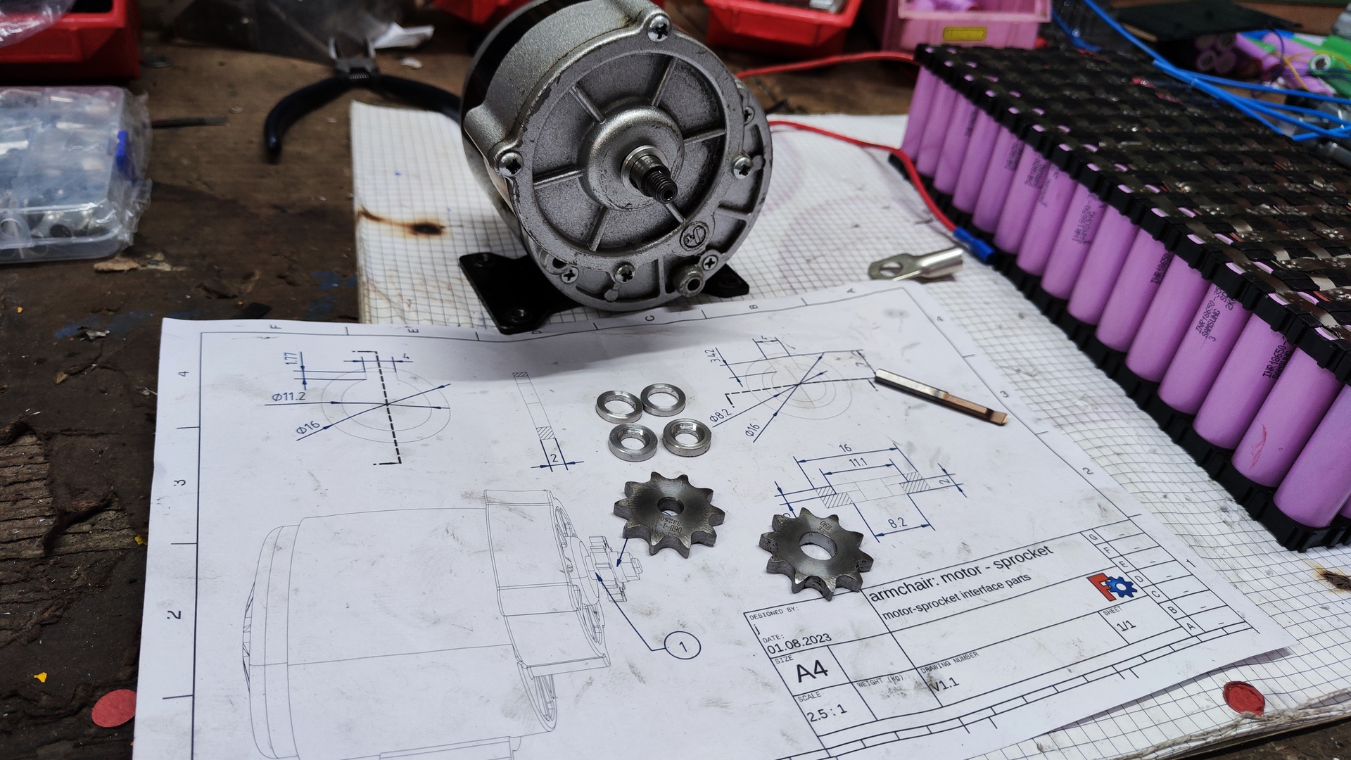
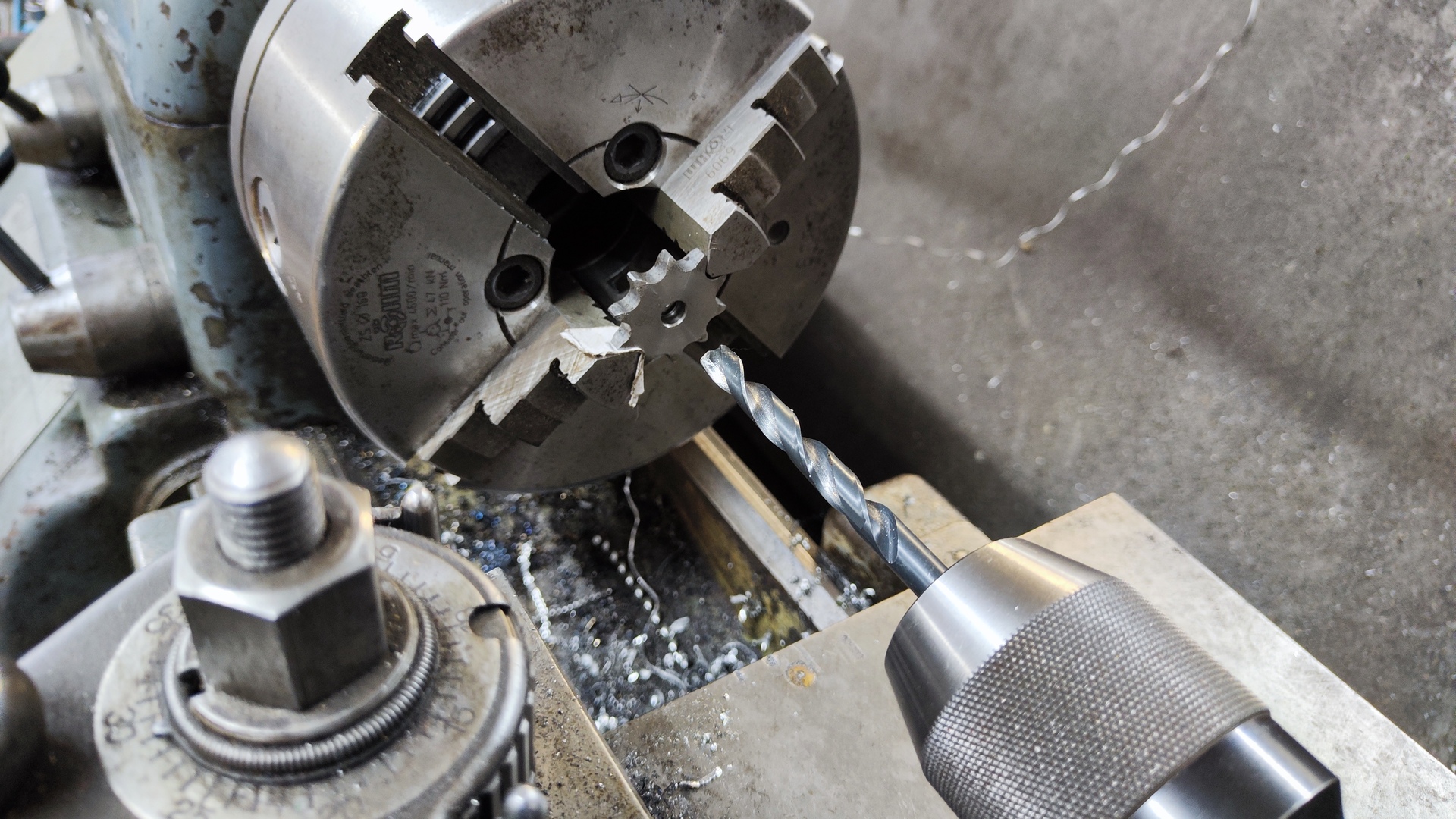
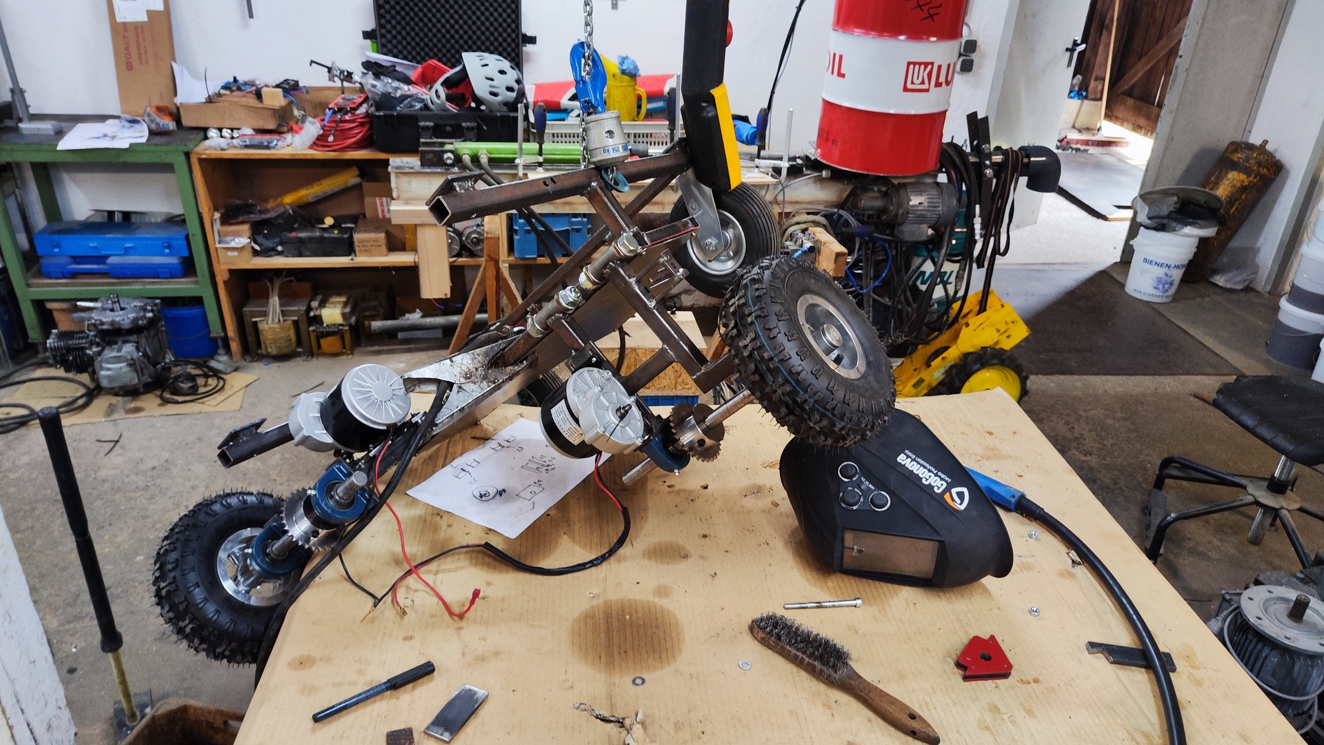
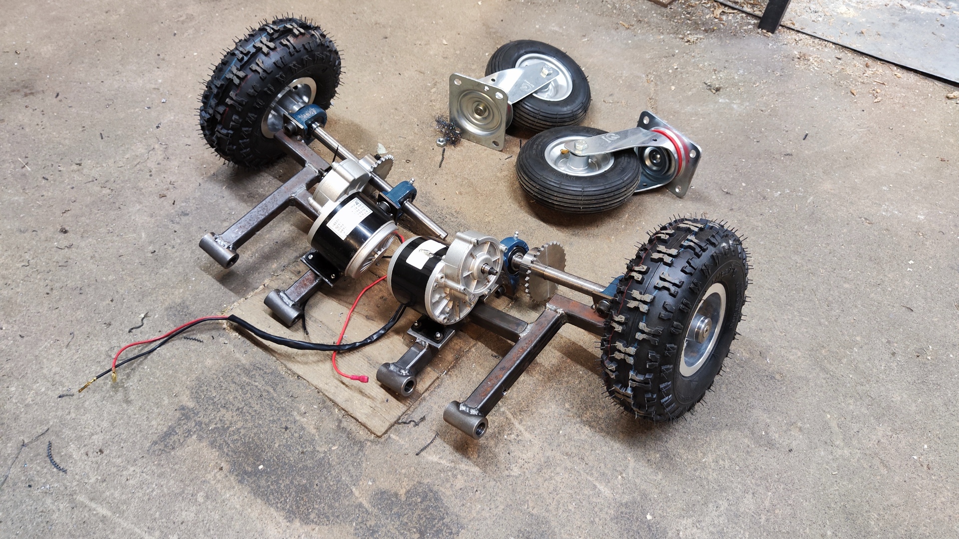
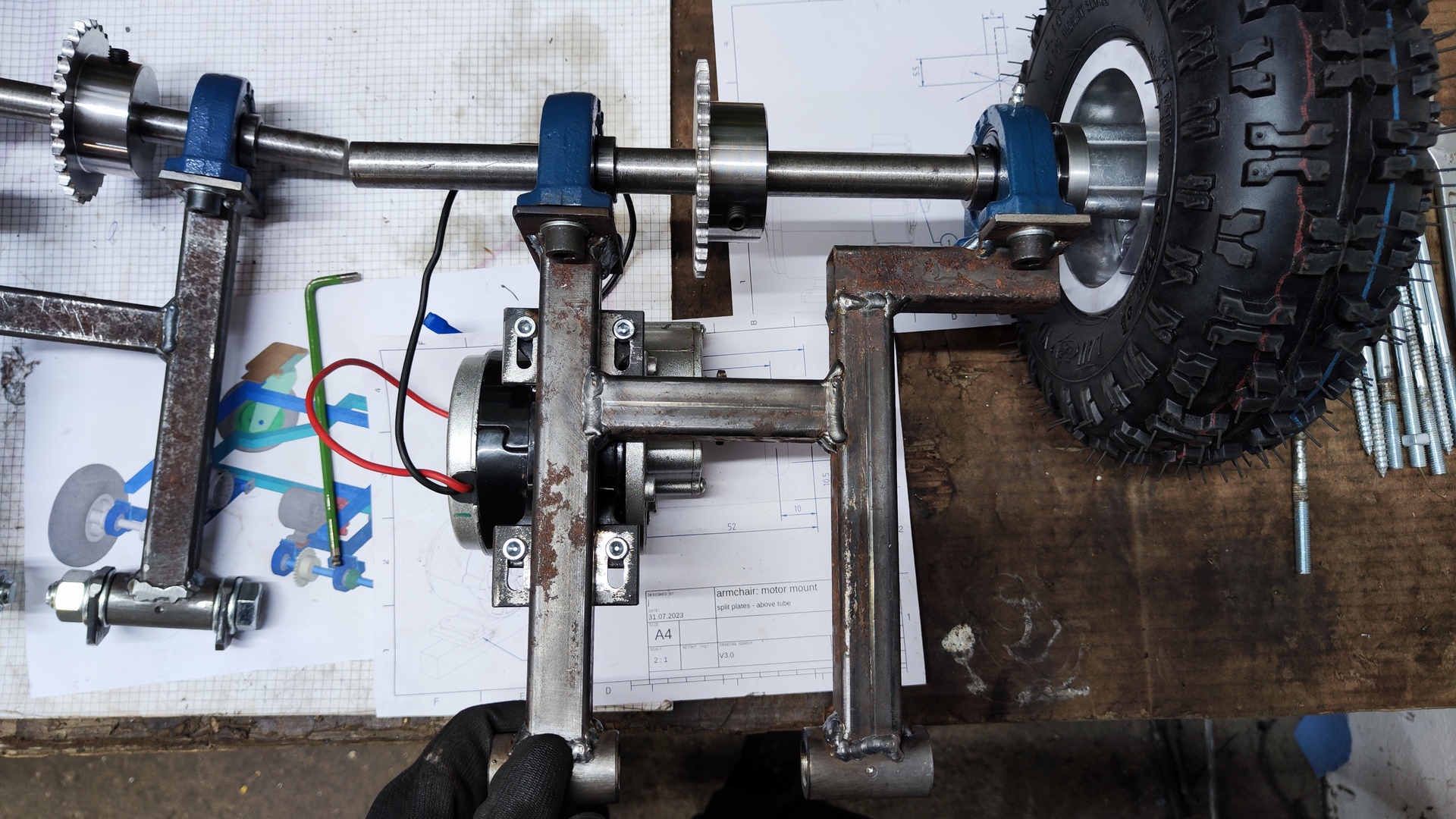
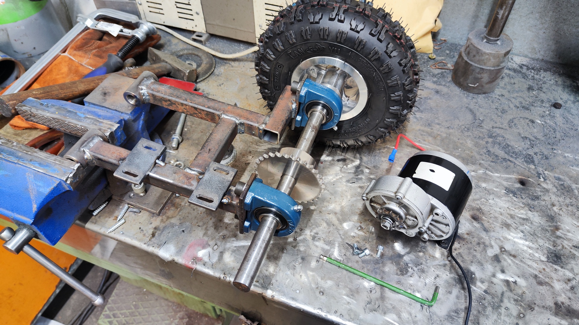
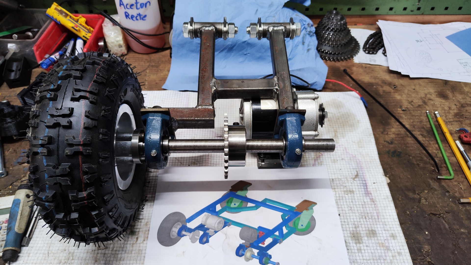
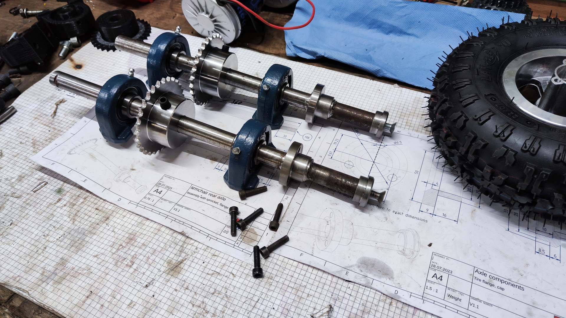
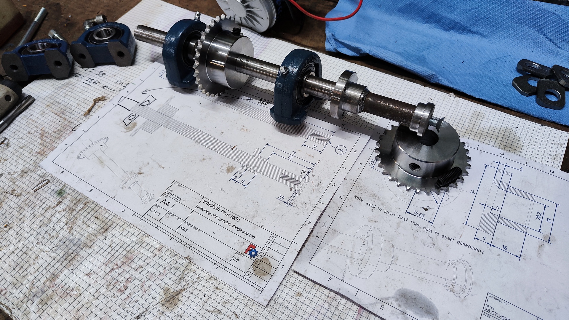
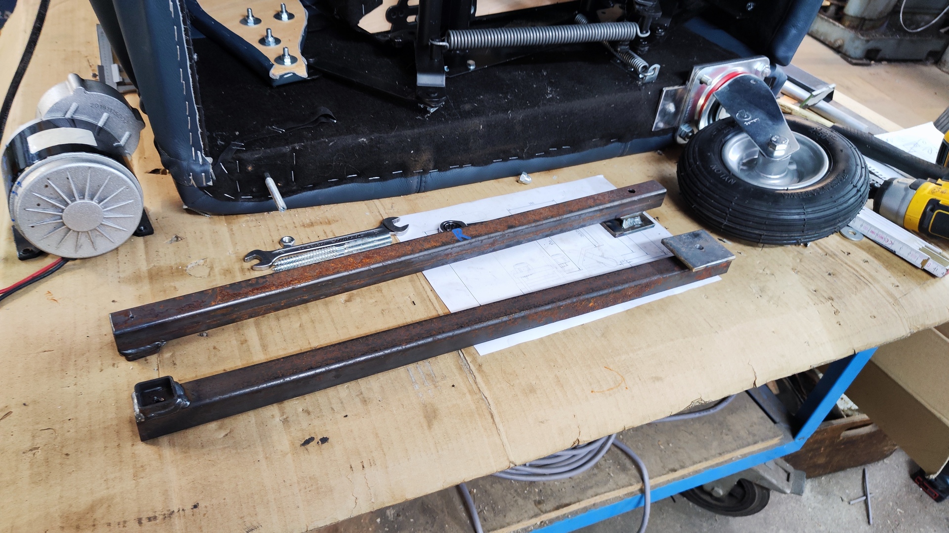
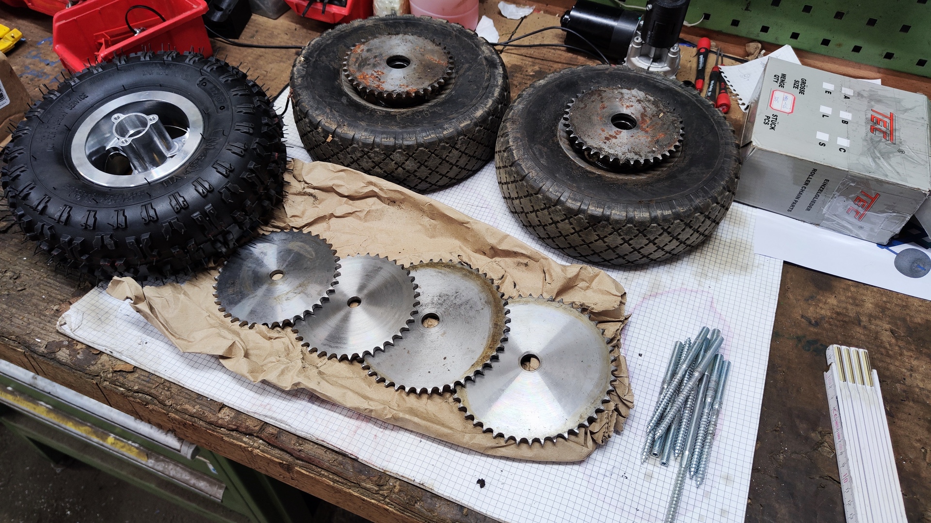
Drivetrain:
- Chain: 06B-1(3/8’ x 7/32’)
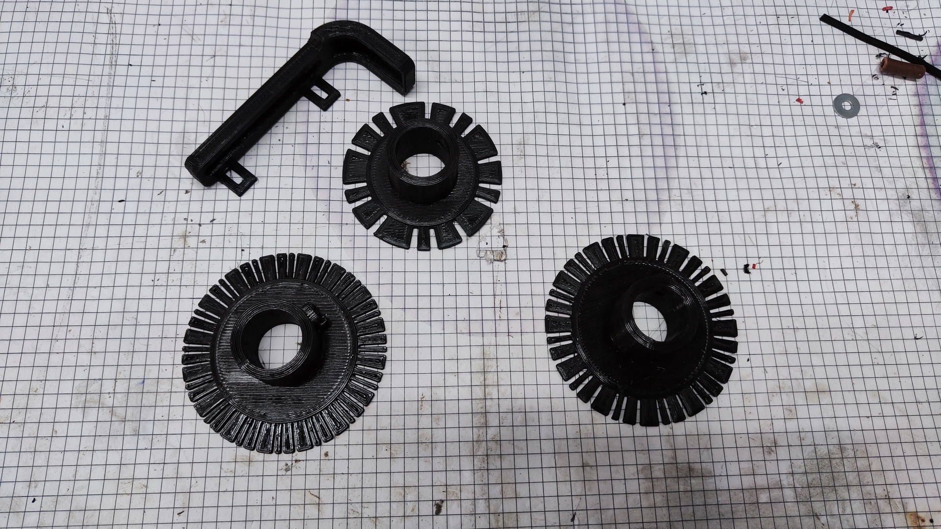
- Sprockets:
- Motor: Z10
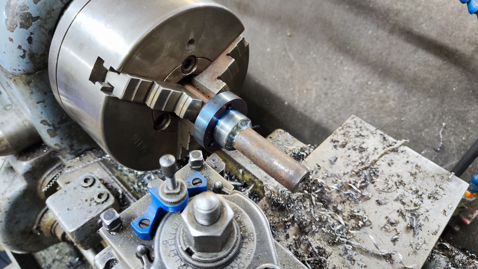
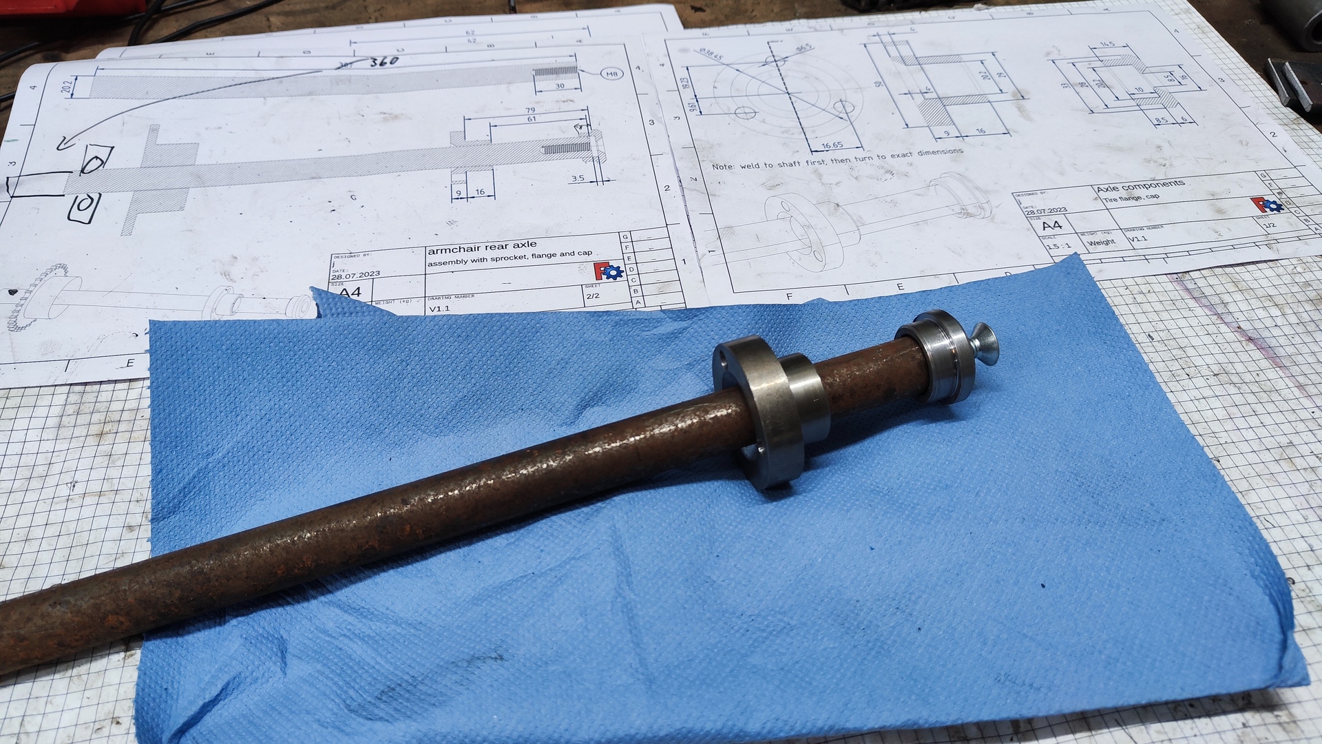
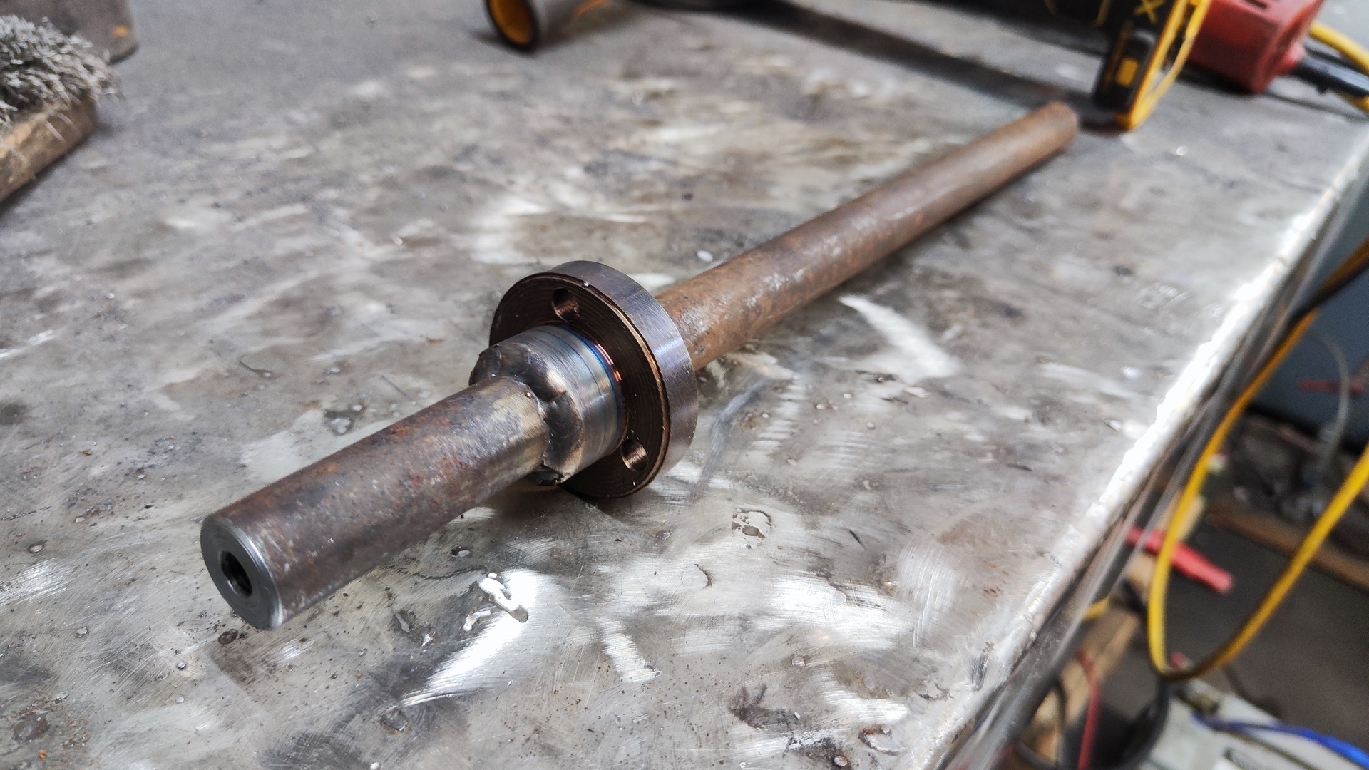
- Axle: Z30
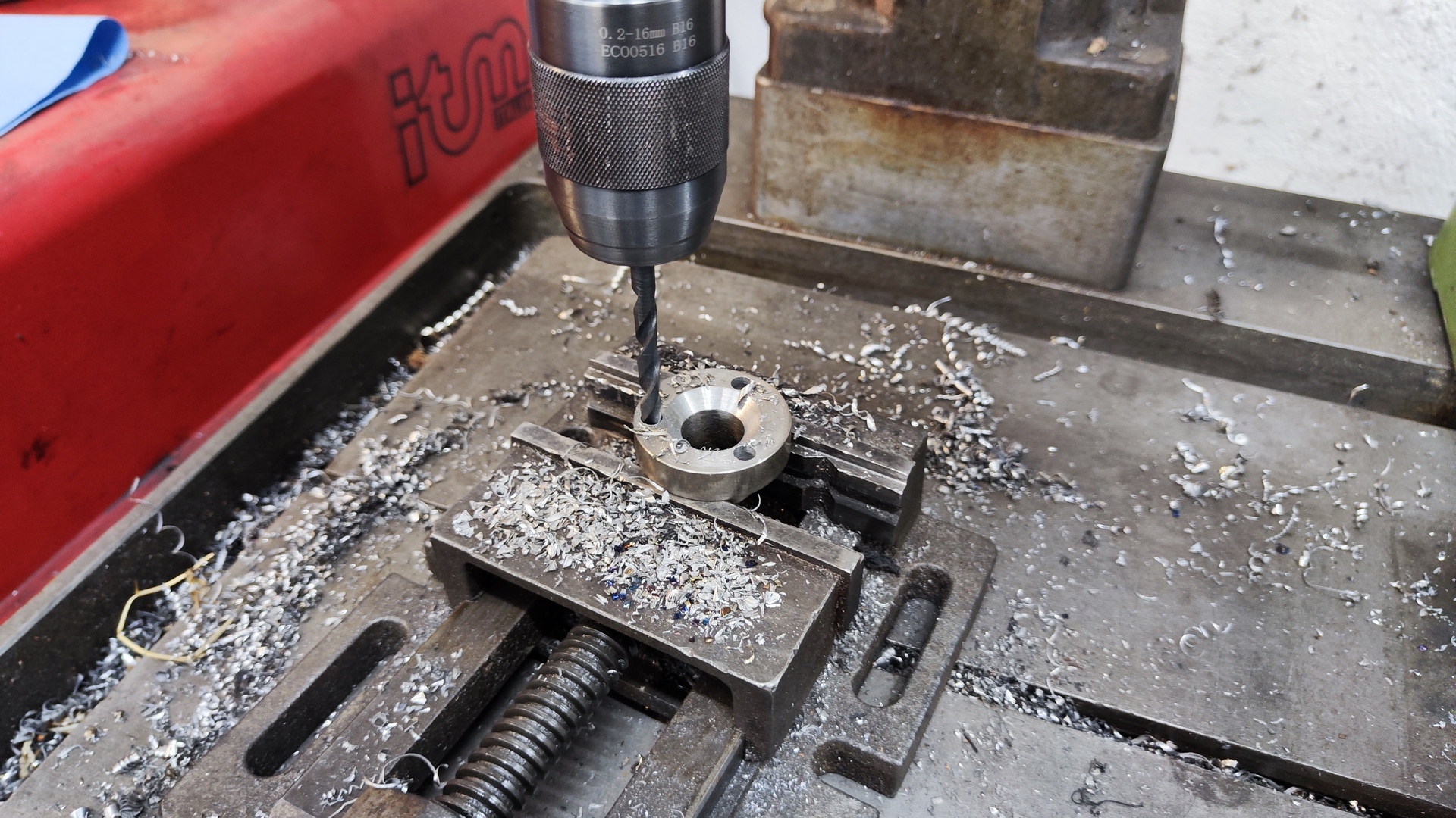
- Axle diameter: 20 mm
-
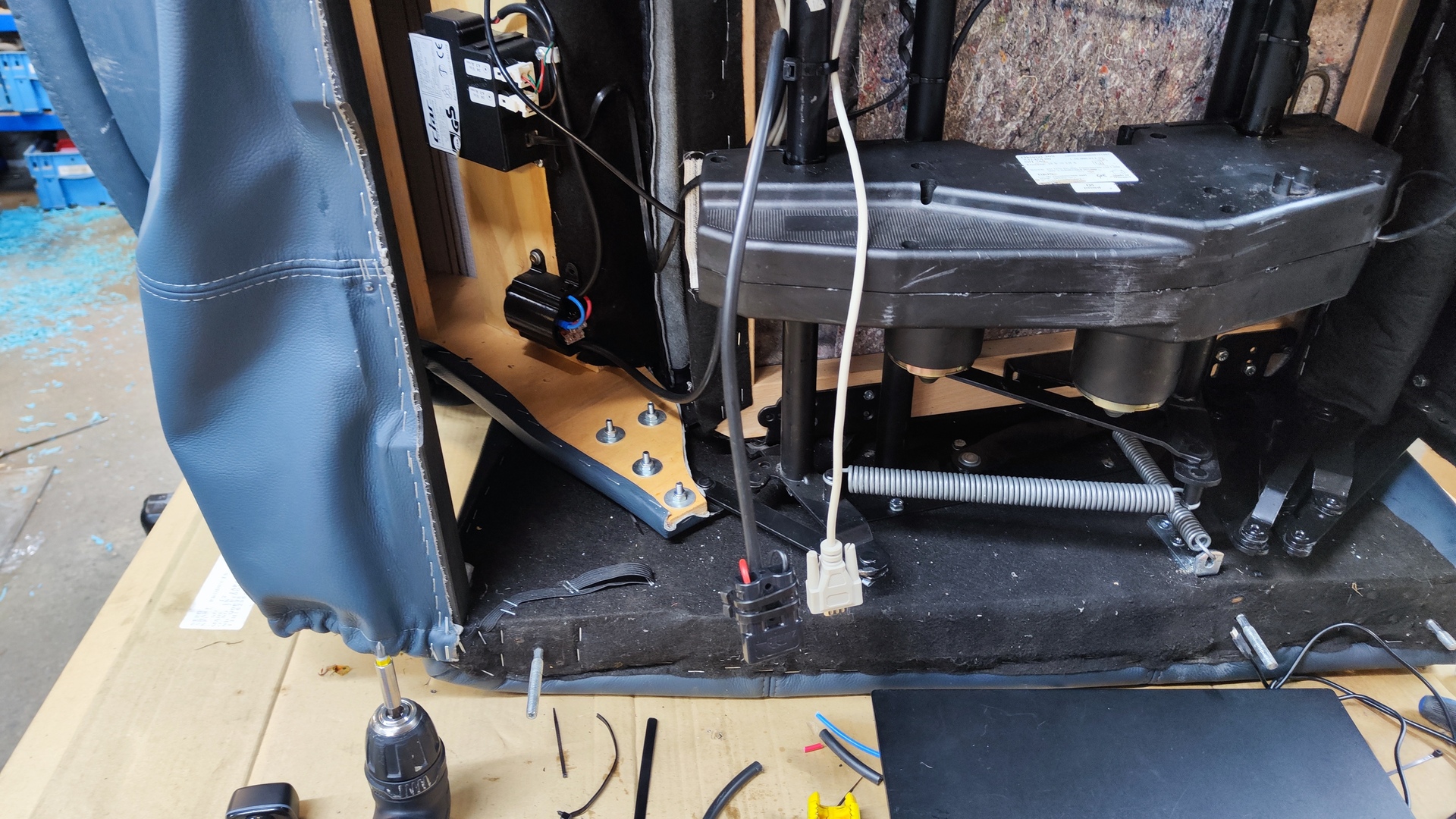
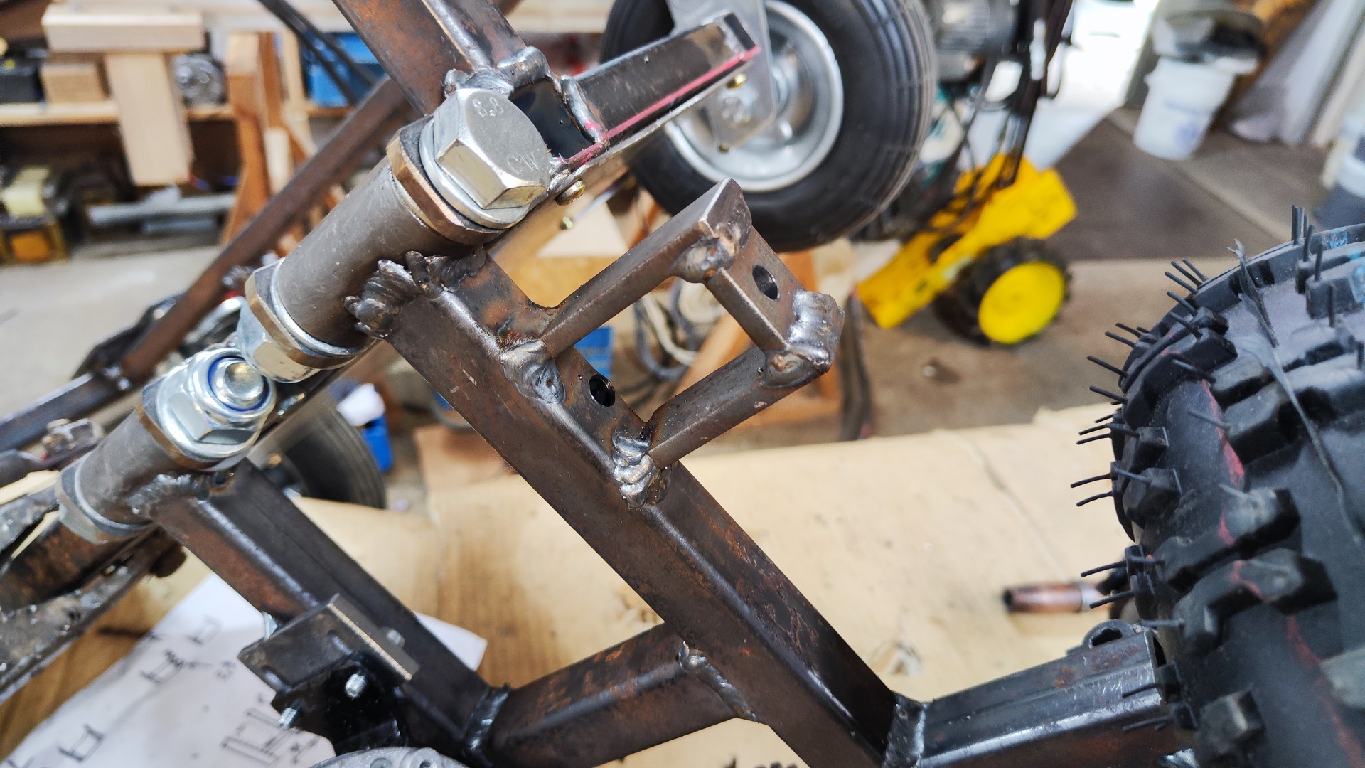
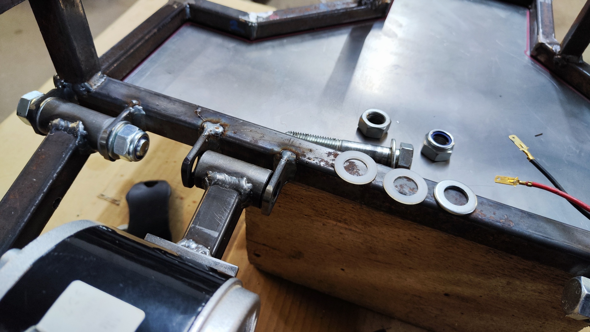
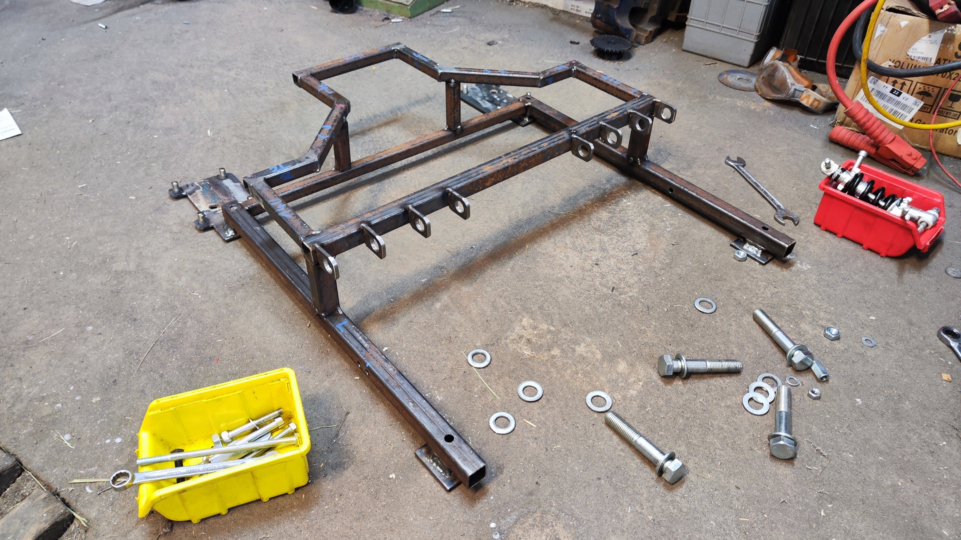
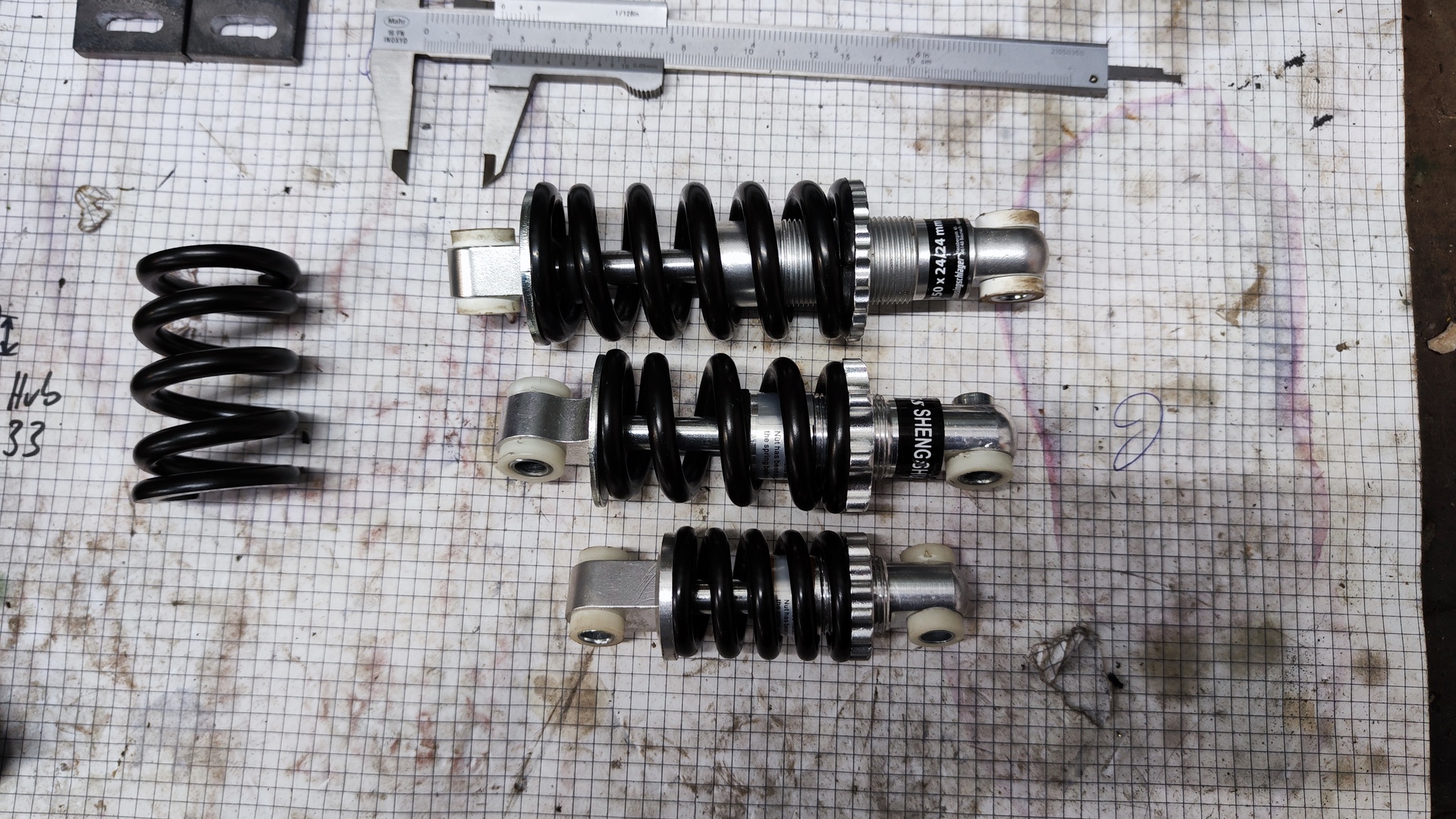
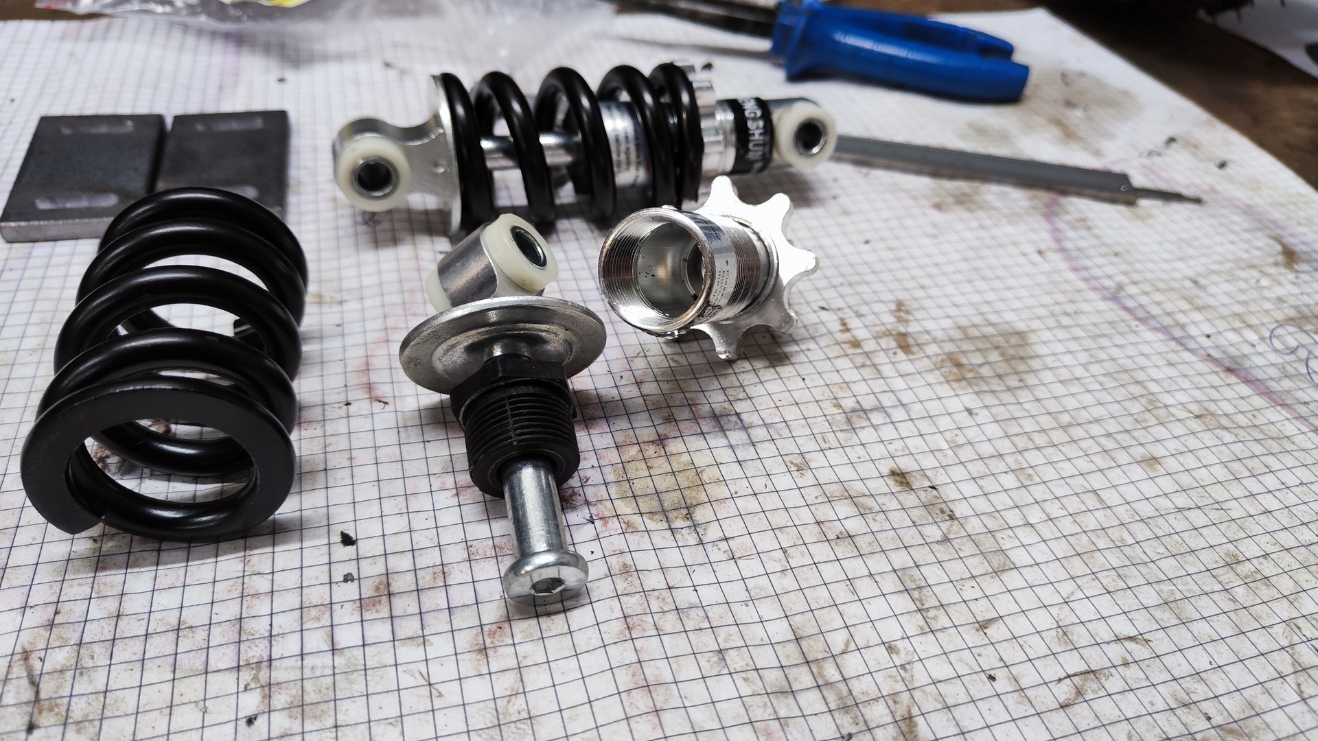
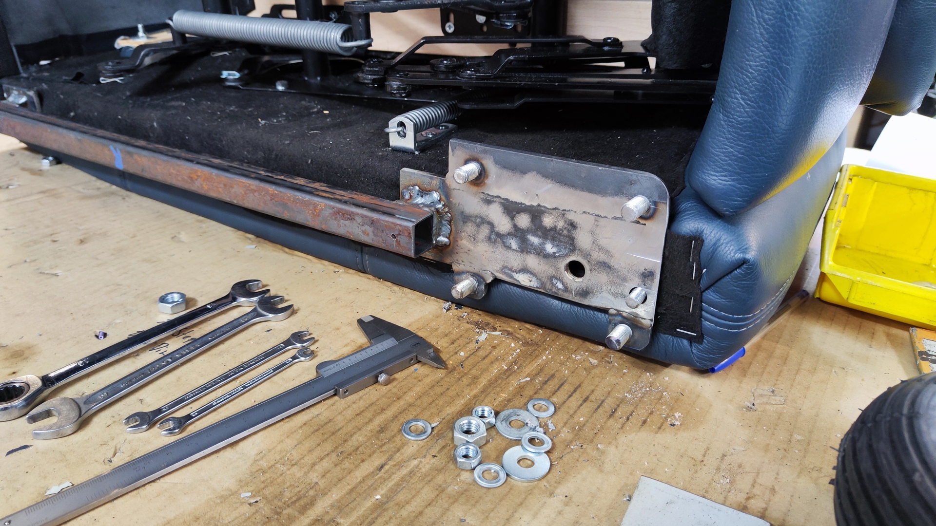
Shock absorbers:
- Length: 125 mm
- Spring: 750 lbs
- Type: Spring-only (no dampener)
-
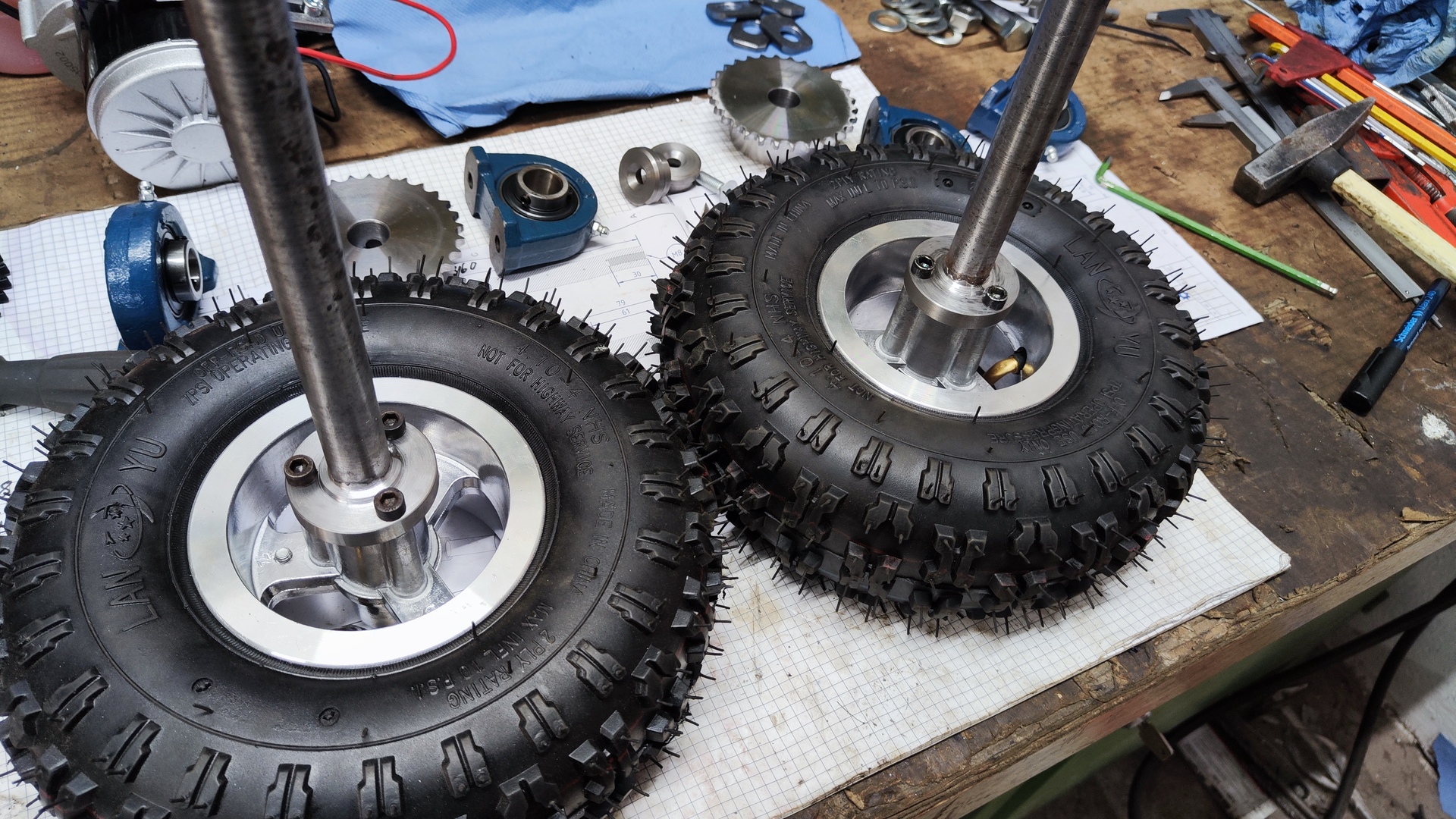
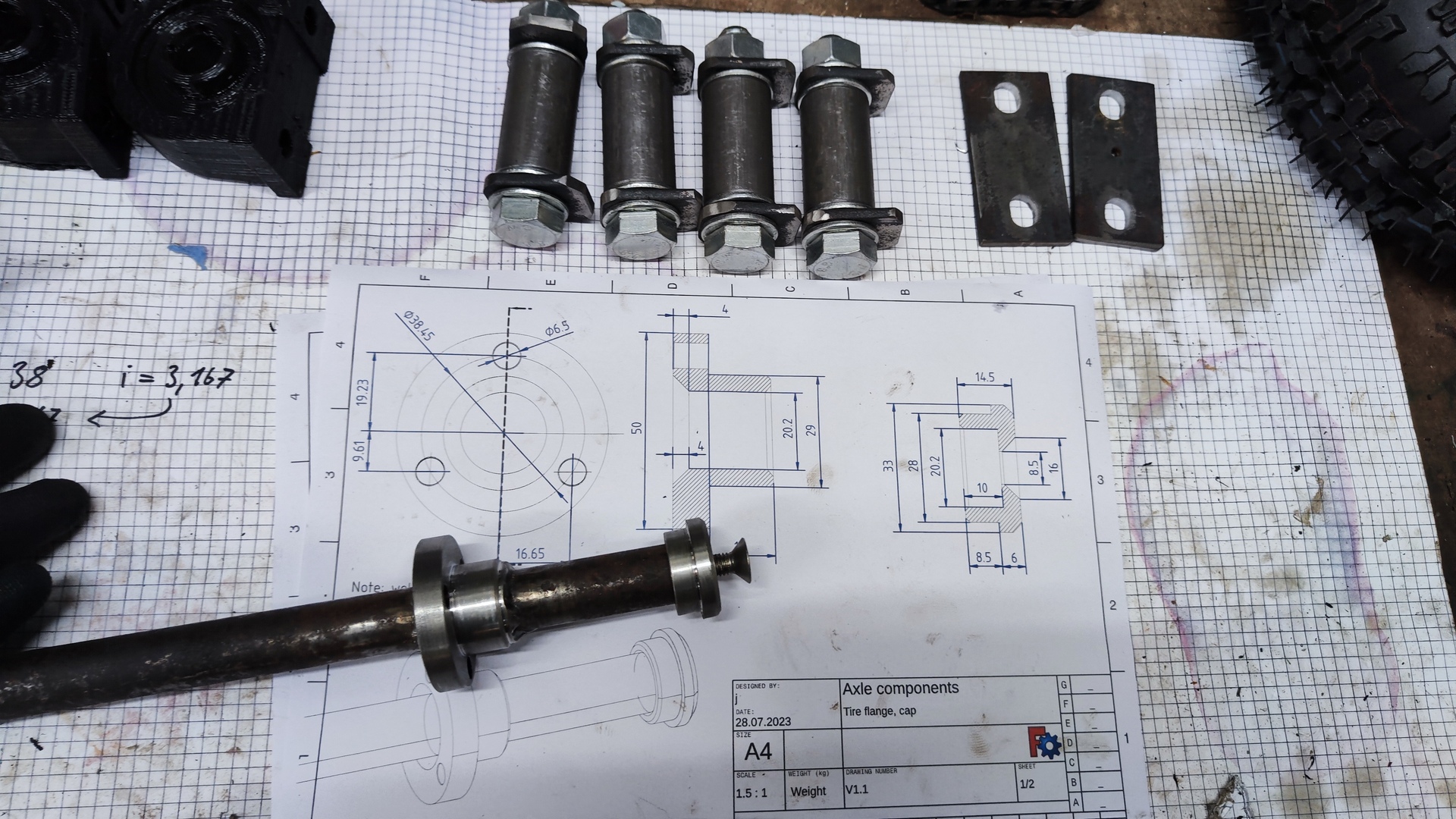
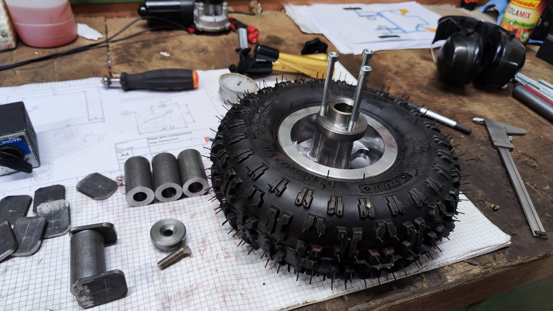
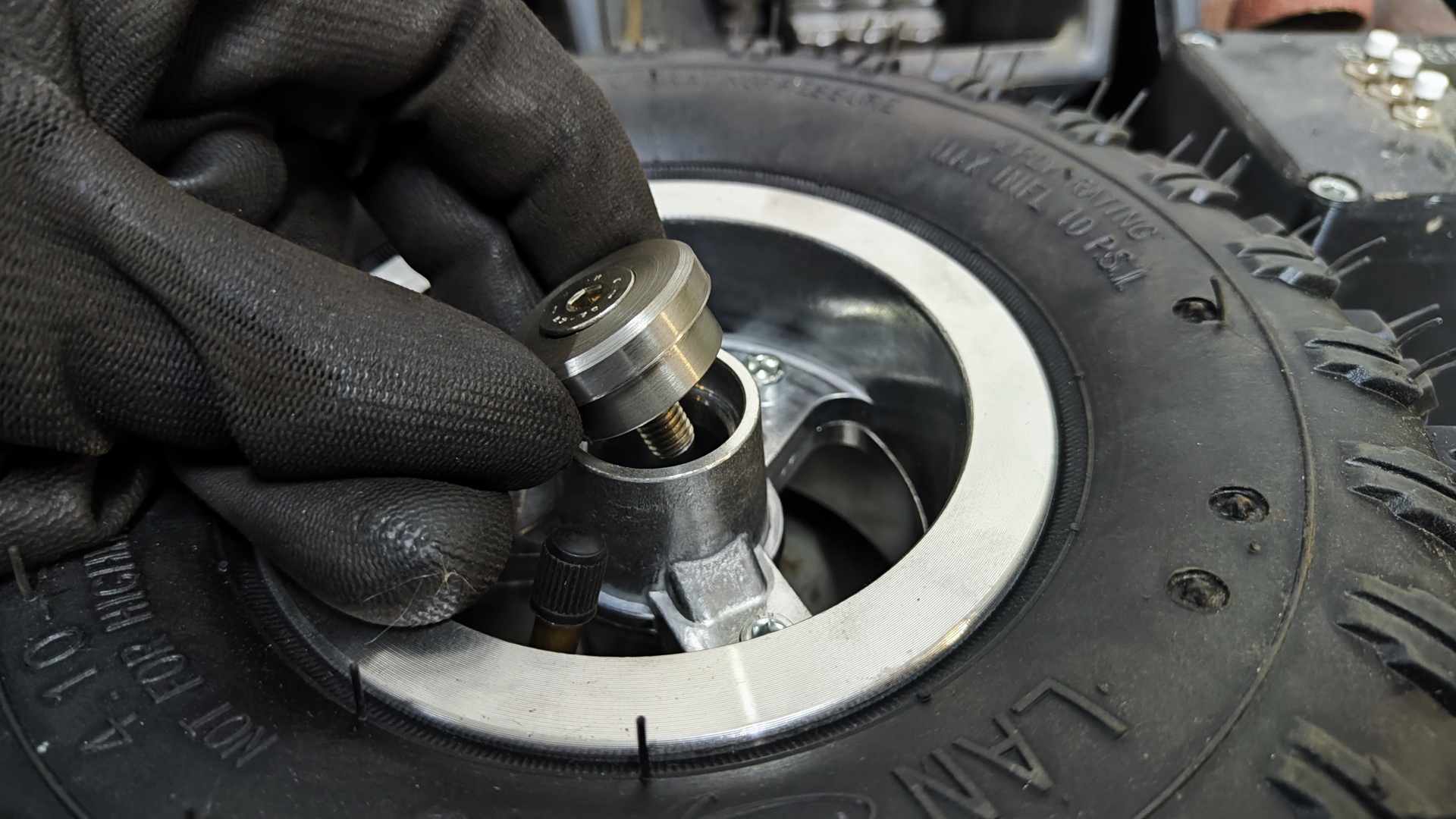
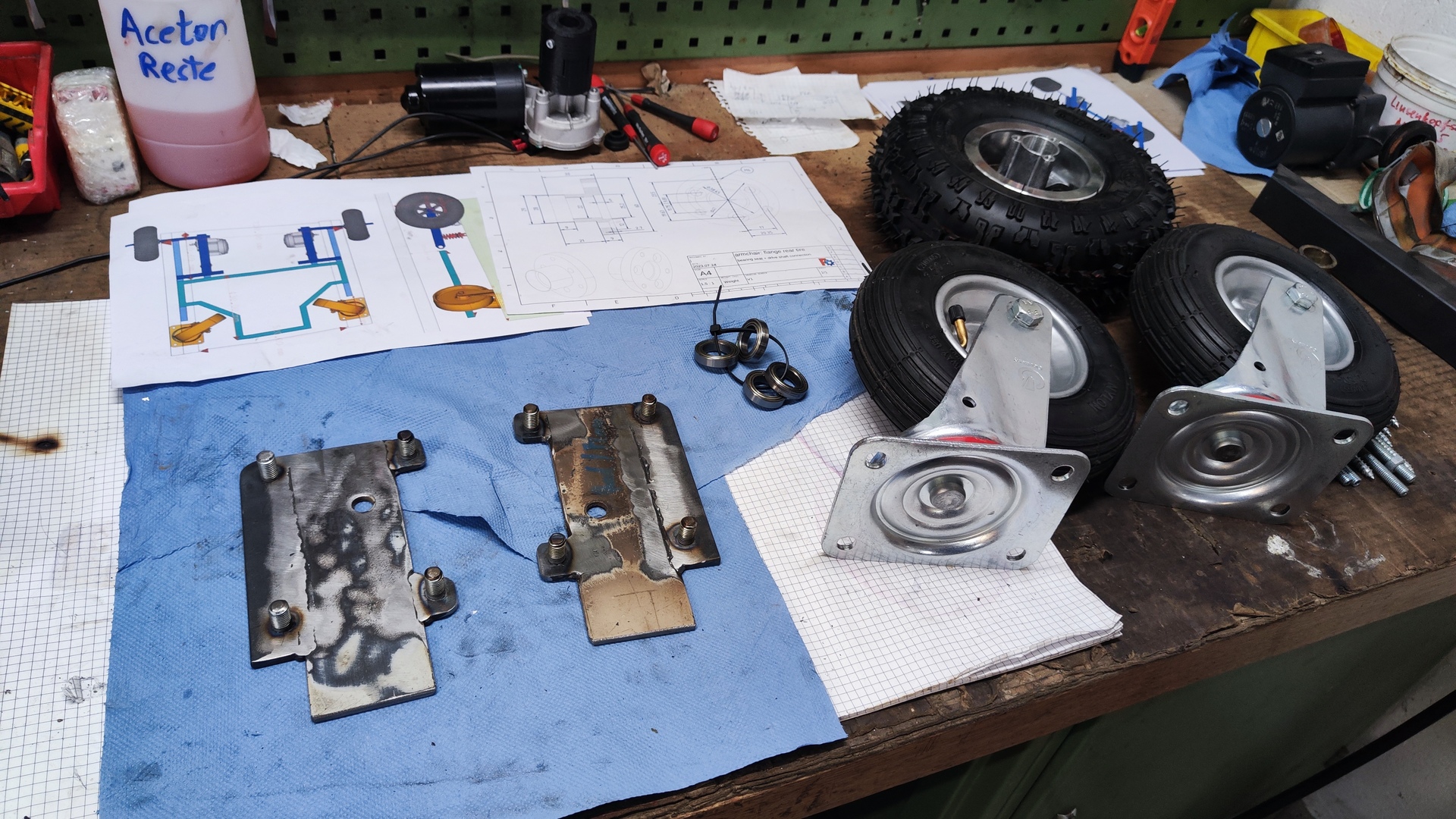
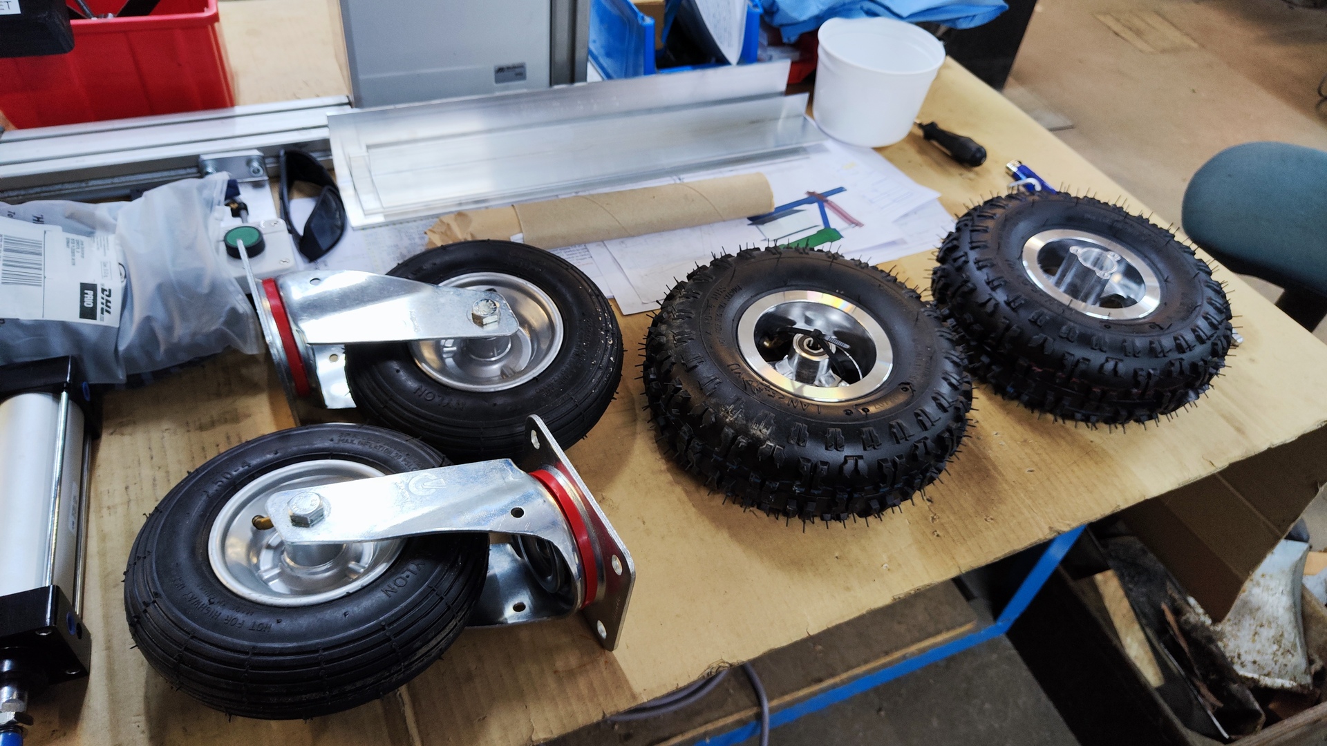
Tires:
- Rear:
- Type: 4.10-4 for Mini-Quad
- Diameter: 250 mm
- Width: 76 mm
- Max load: 80 kg (each)
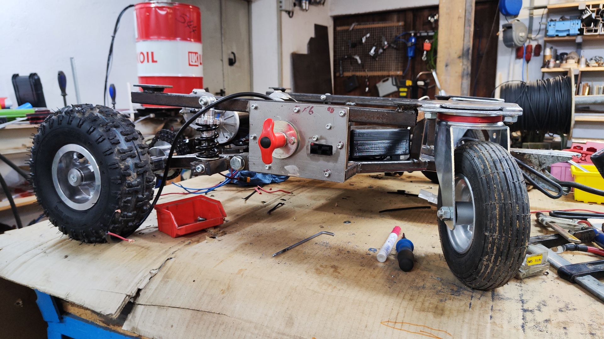
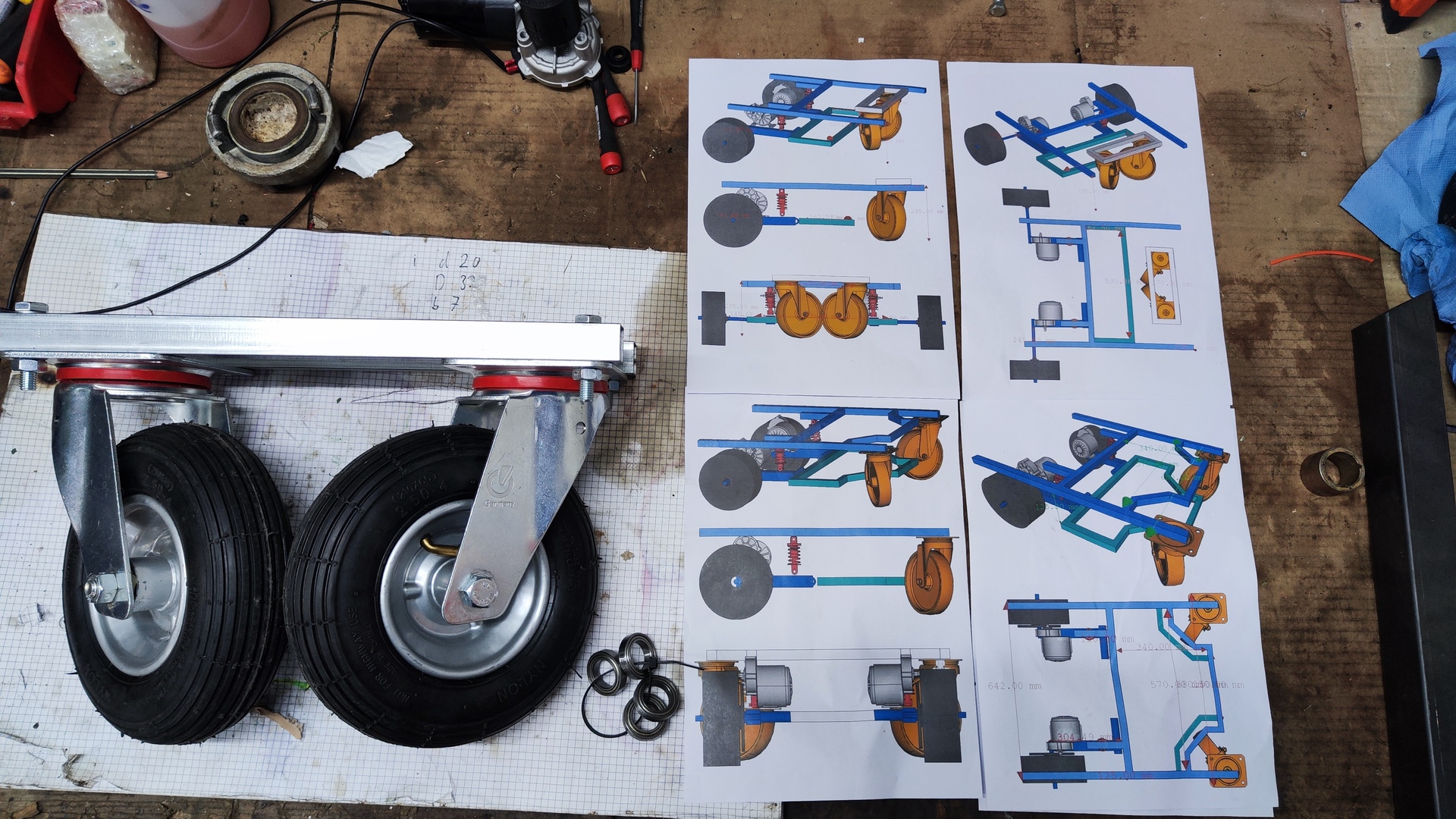
- Front:
- Type: Swivel caster with pneumatic tire
- Diameter: 210 mm
- Height: 250 mm
- Max load: 100 kg (each)
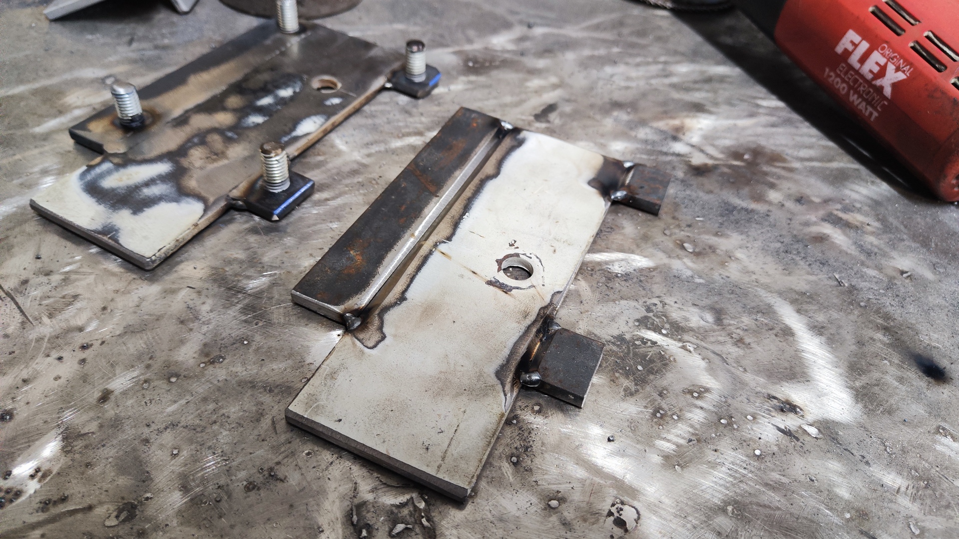
- Rear:
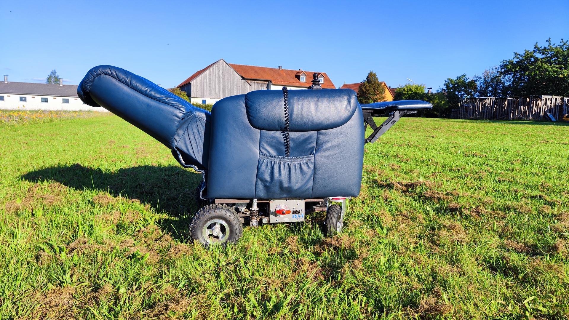
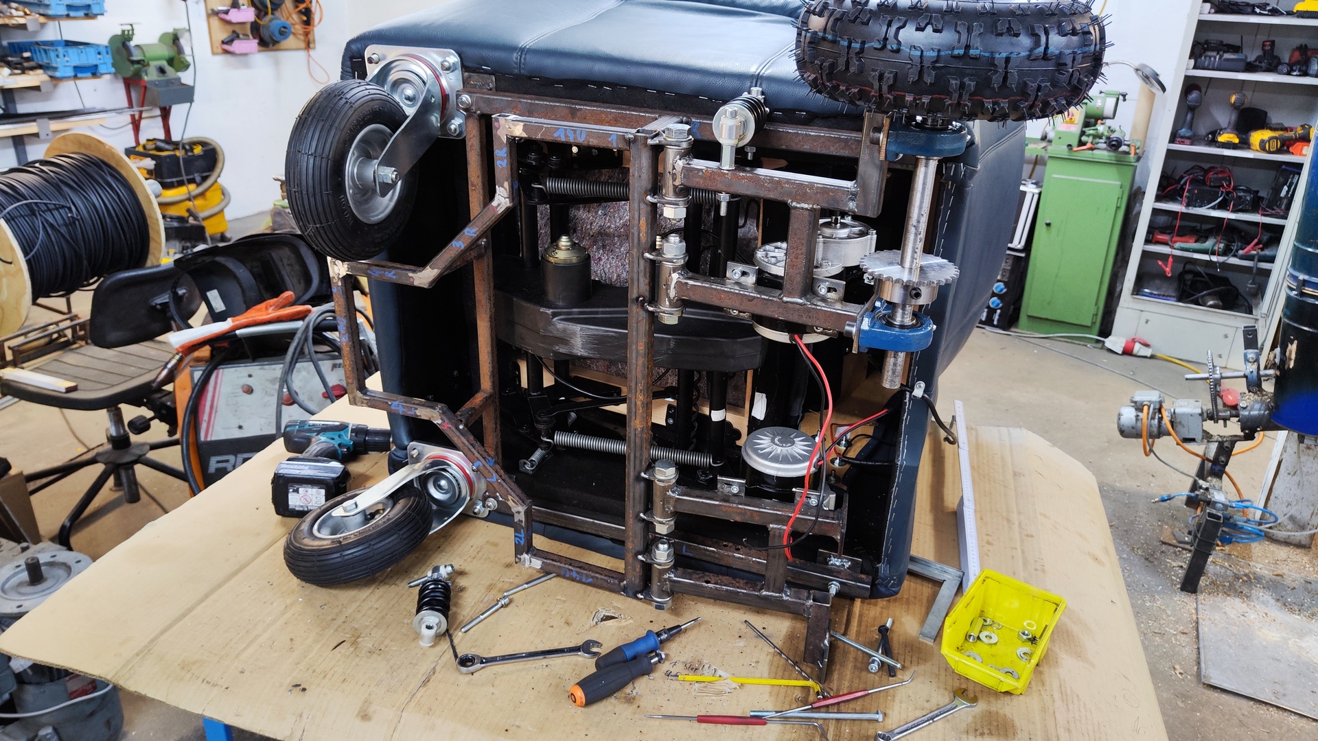
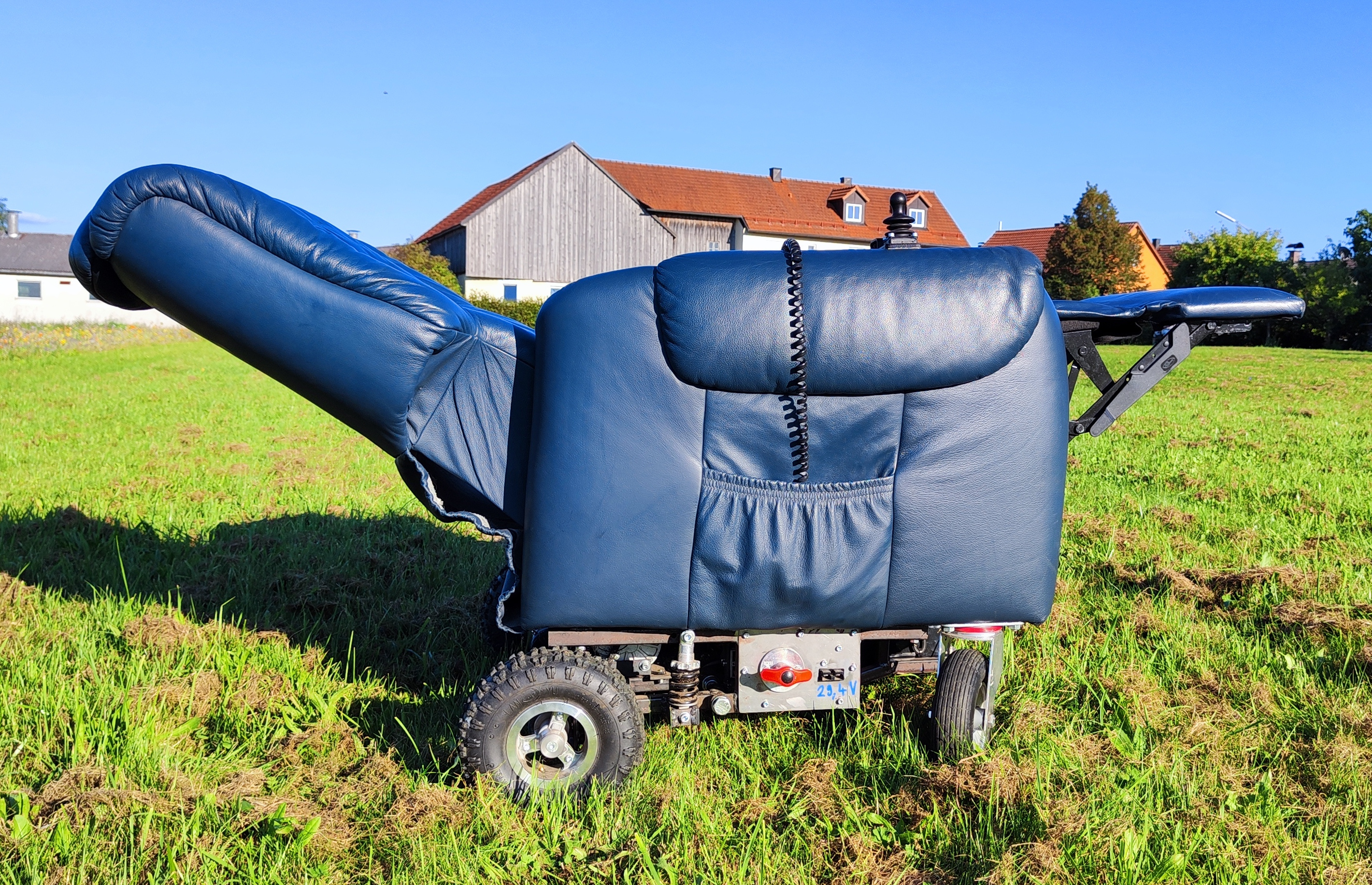
 Rear view
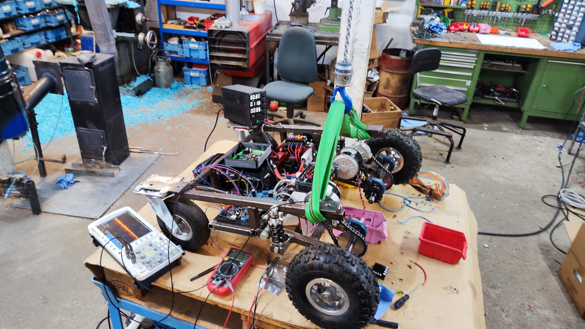
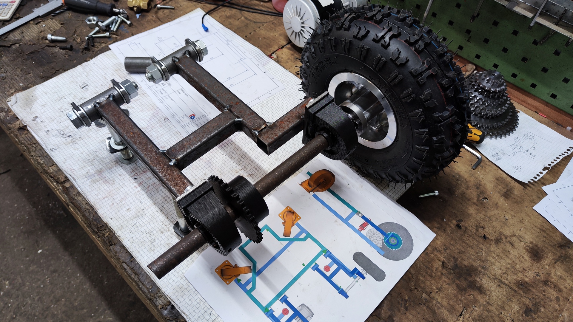
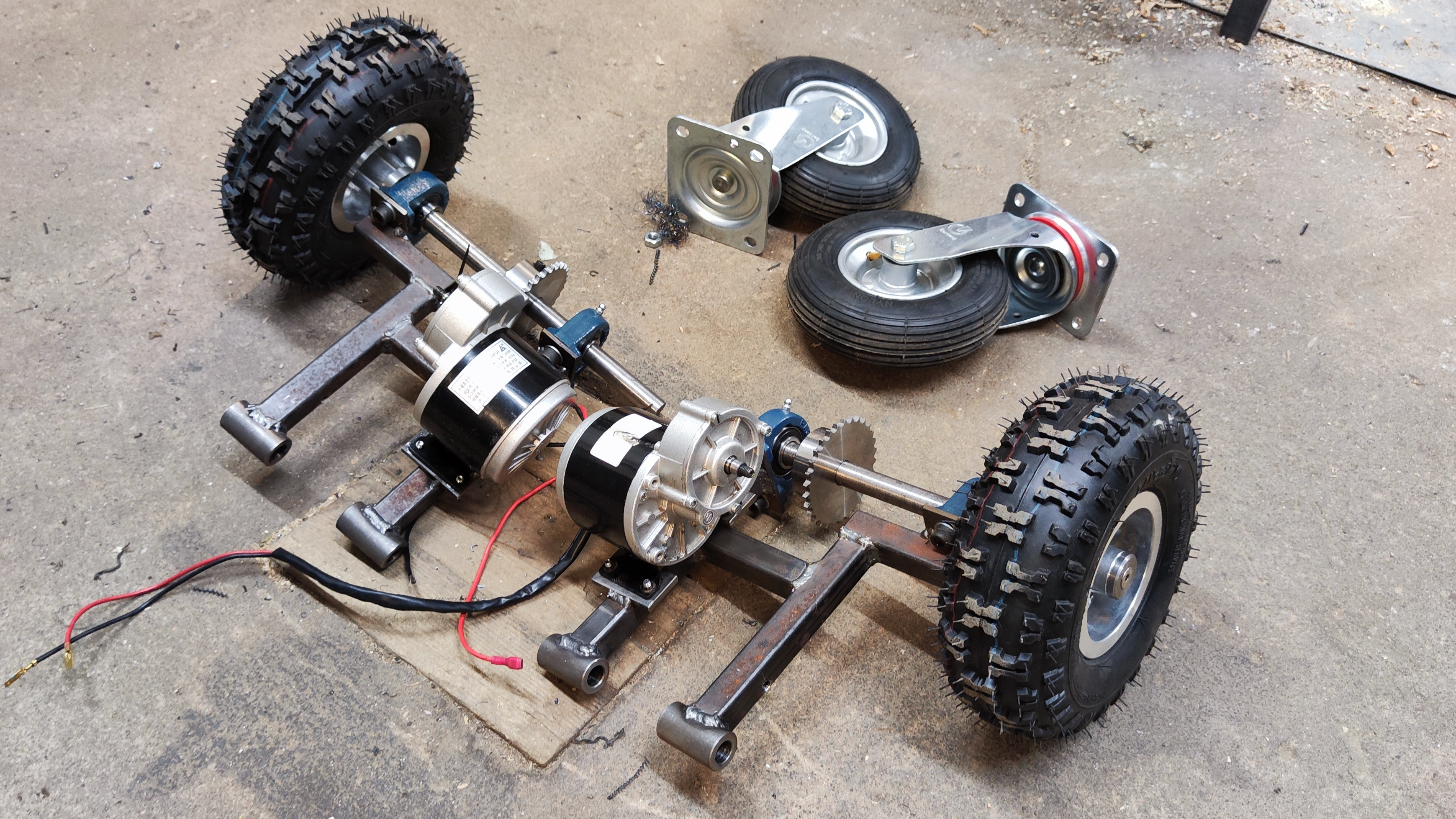 Front tires and rear axle assemblies
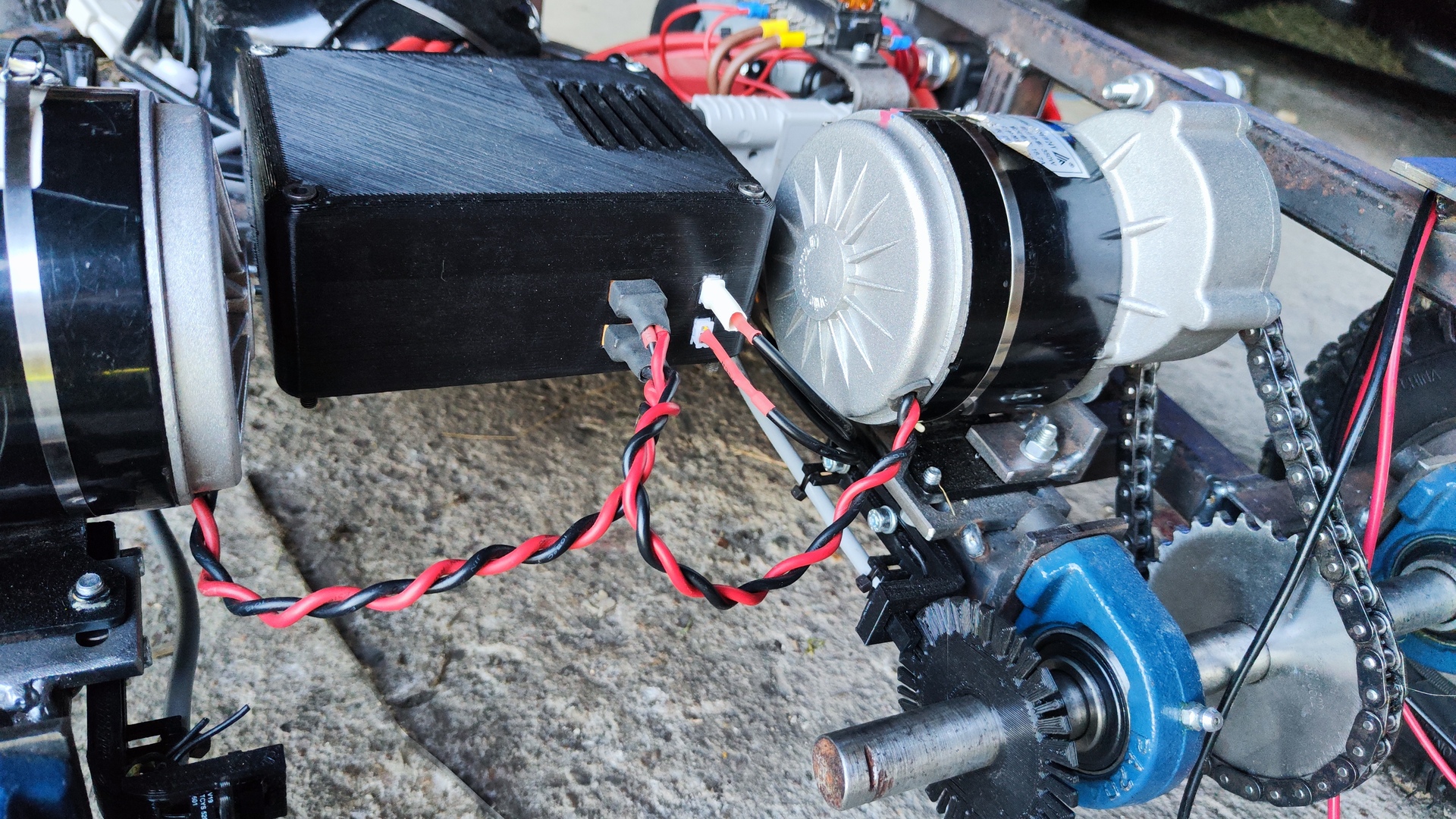
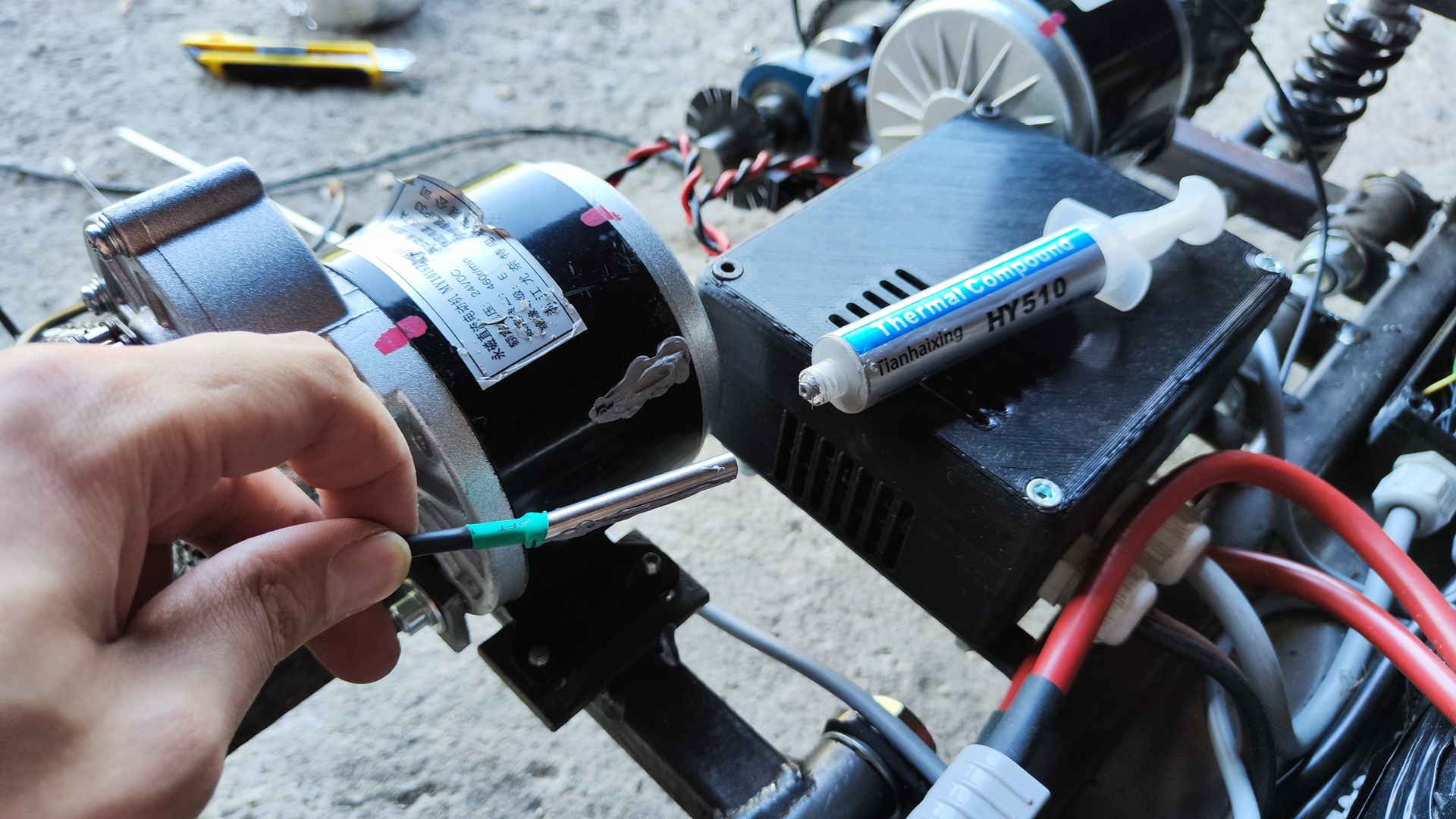
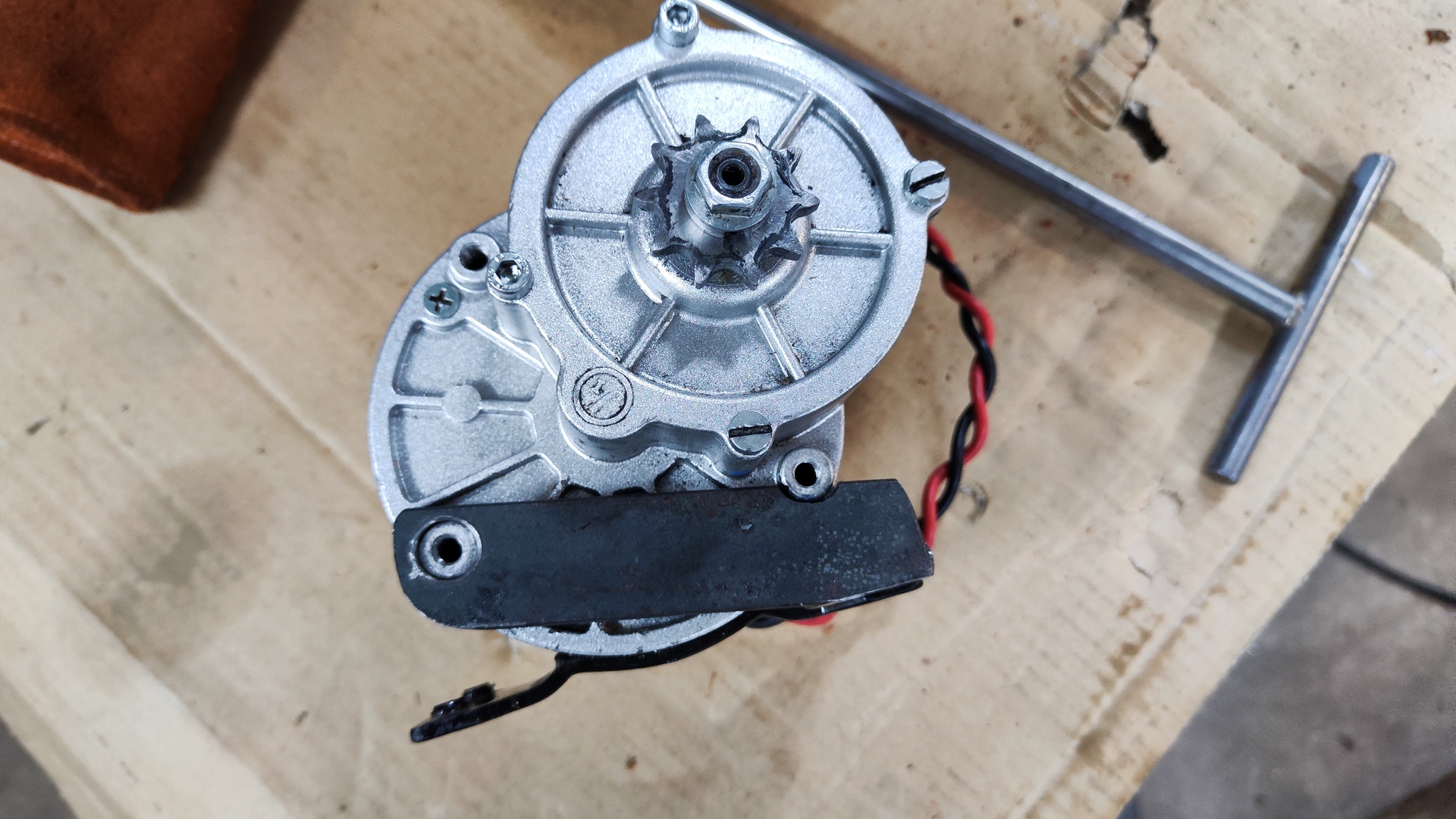
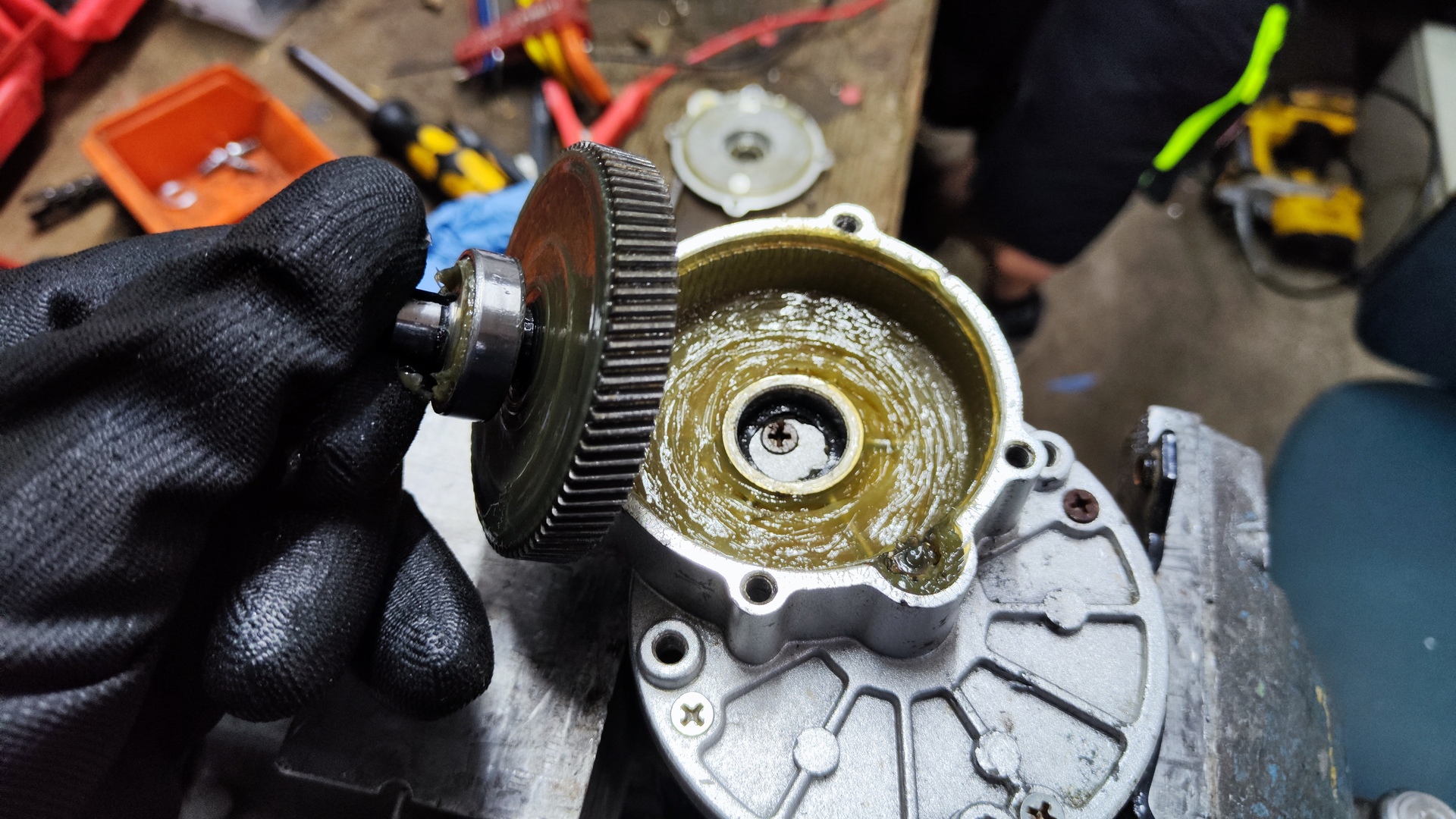
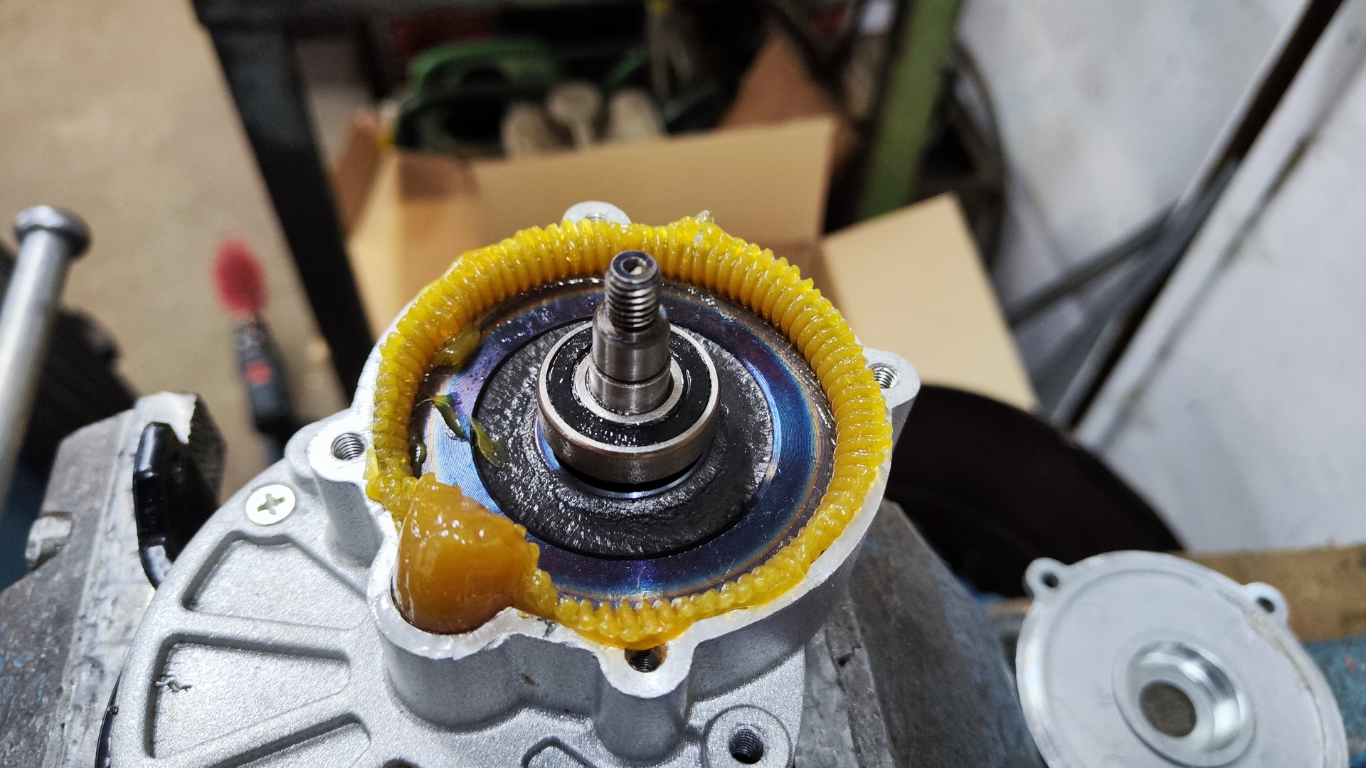
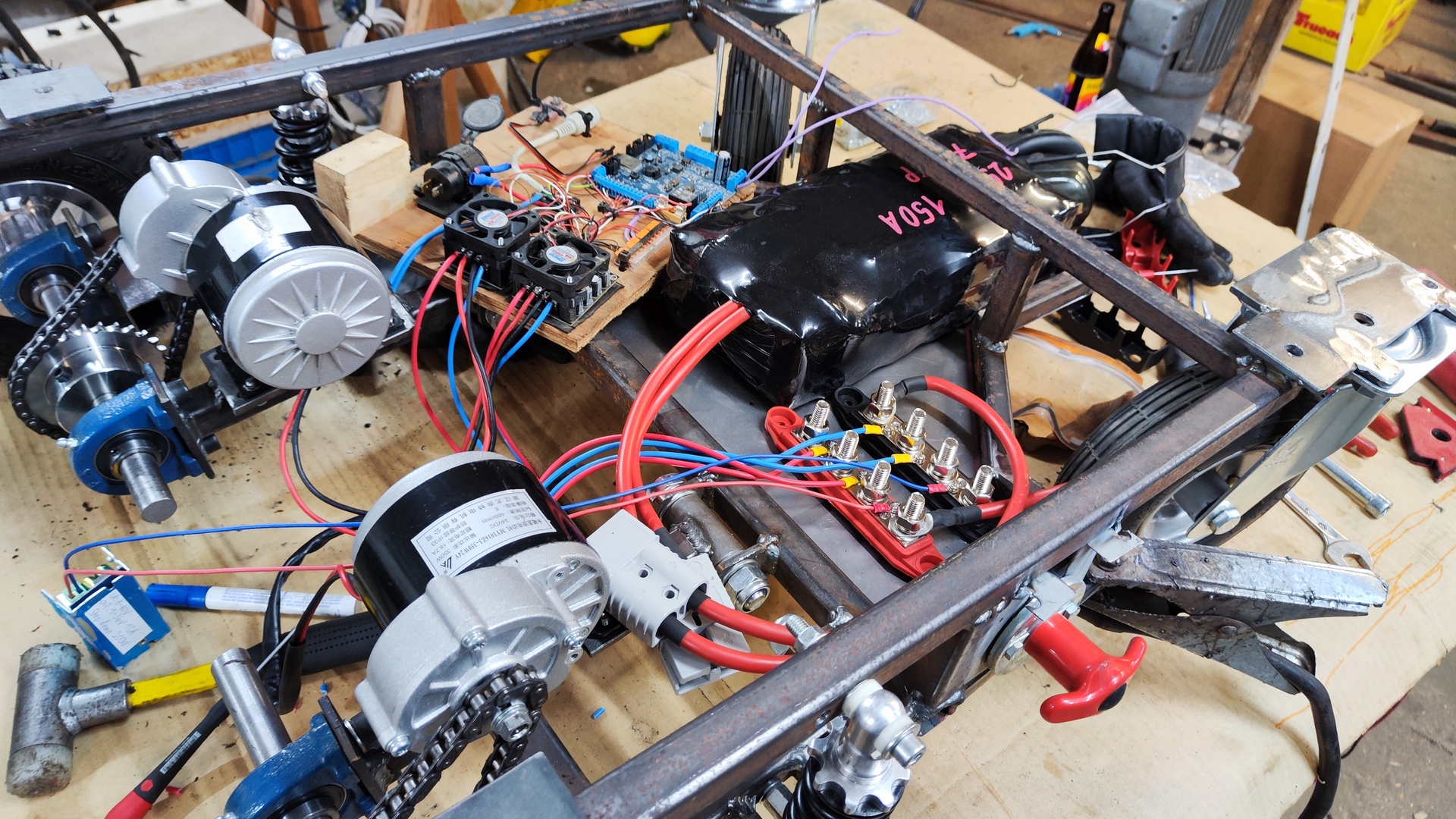
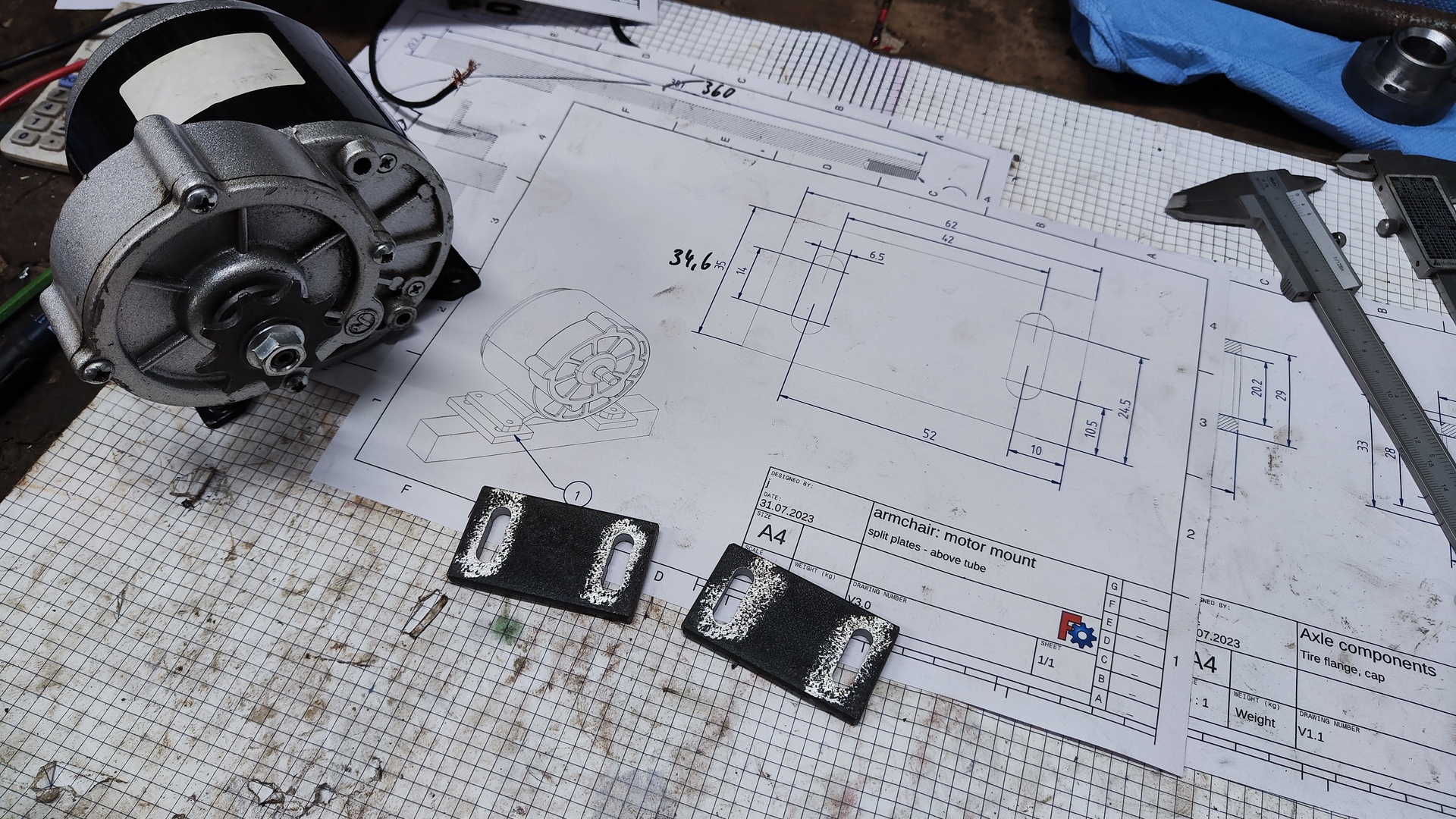
Motors
- Power: 350 W each
- Voltage: 24 V
- Type: Brushed DC motor
- Rotating speed: 2500 rpm (without gearbox)
- Attachment: Gearbox 9.8:1
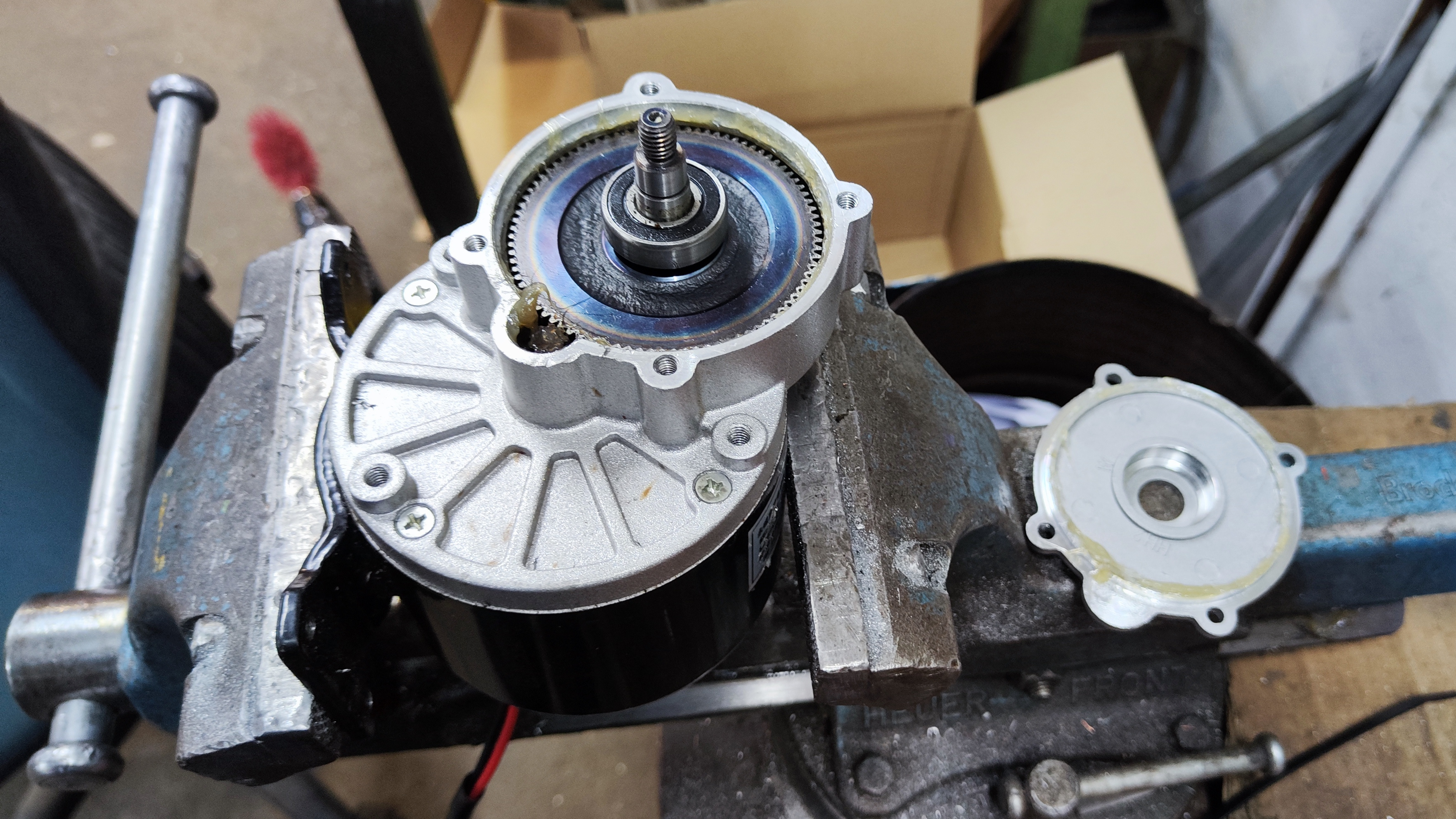 Motor with open gearbox attachment
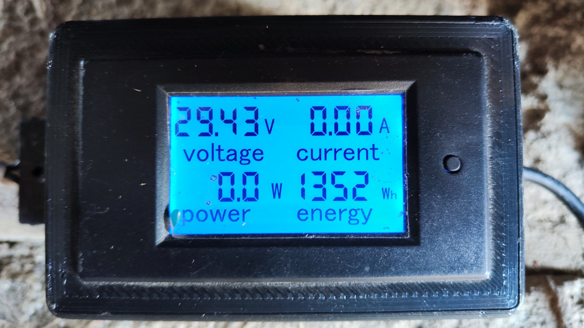
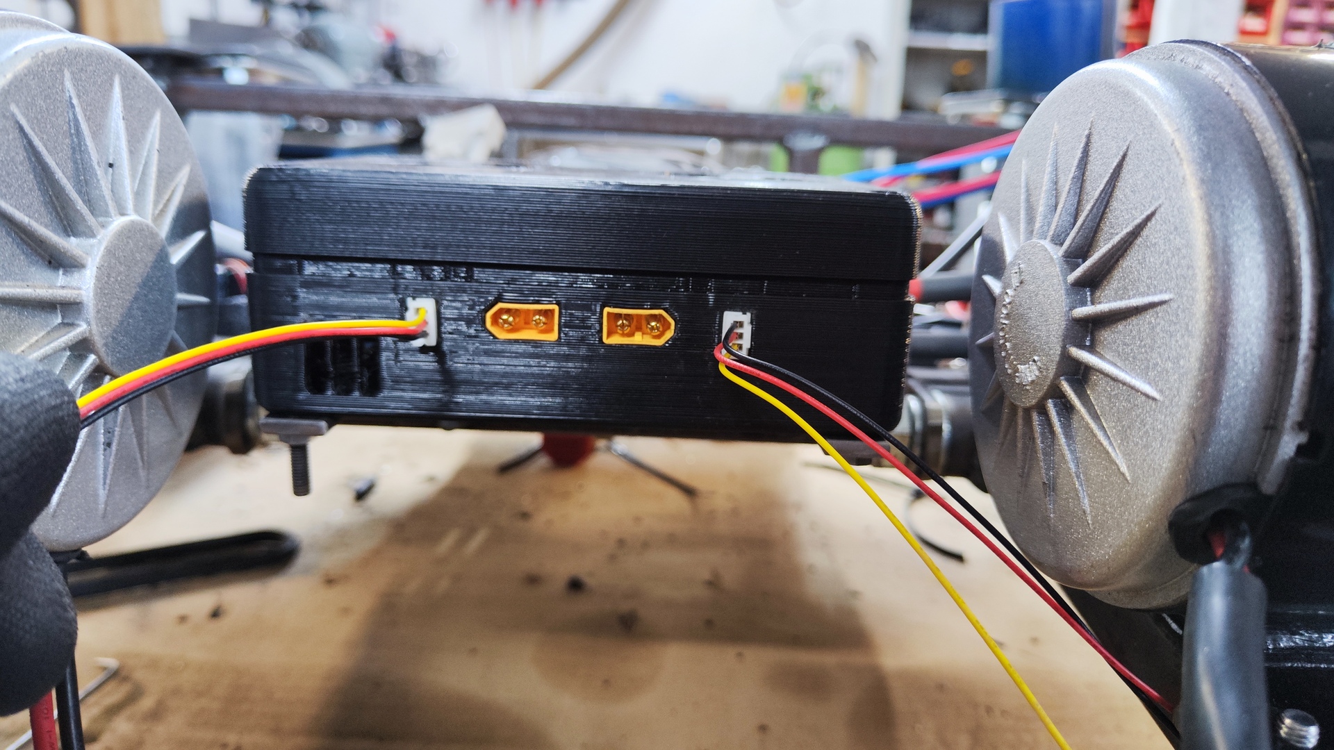
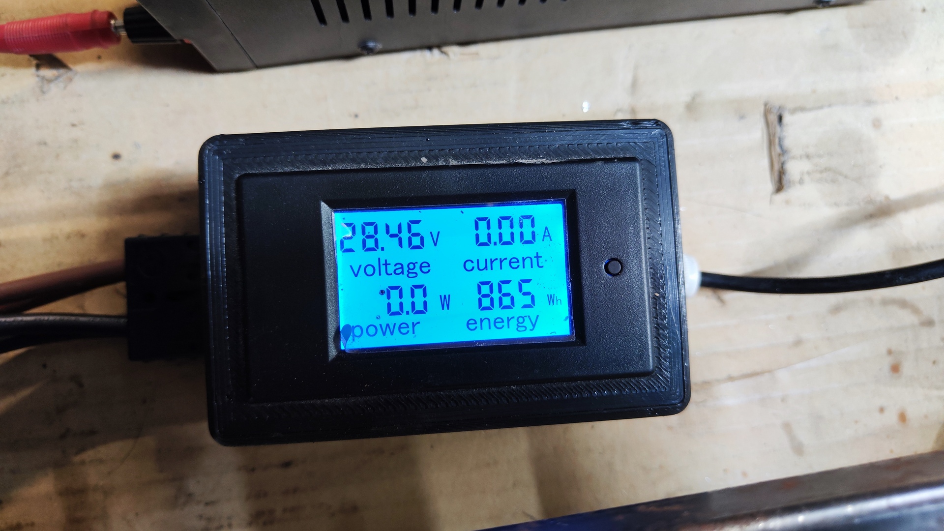
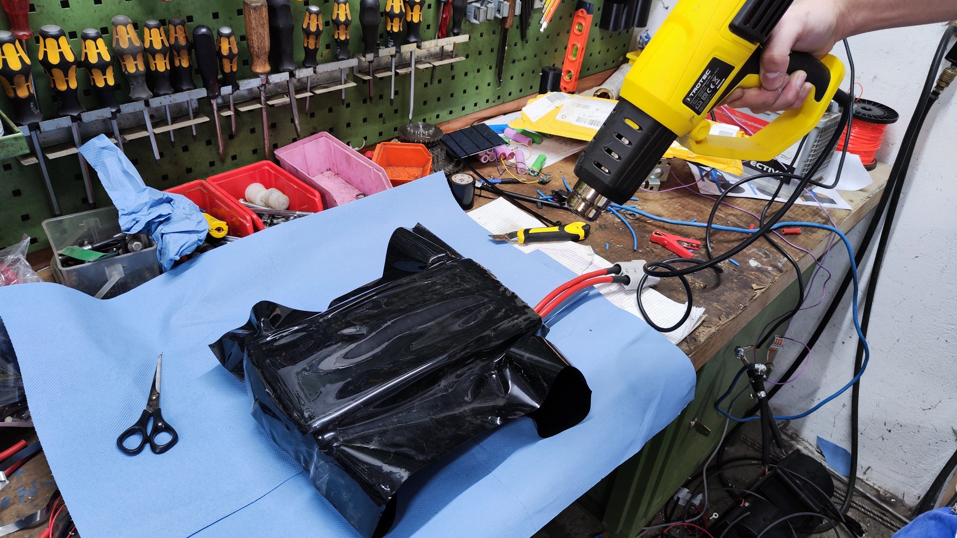
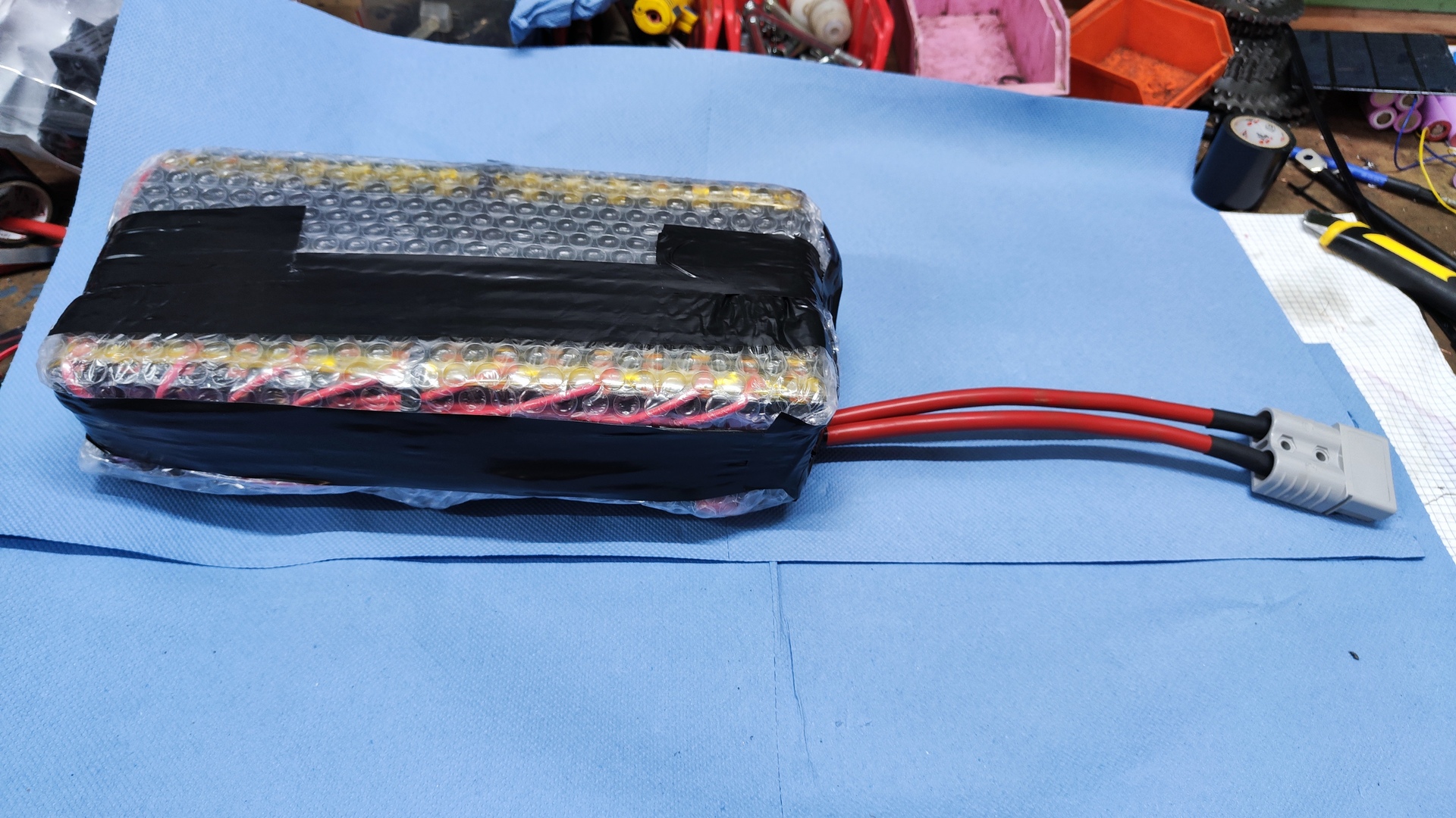
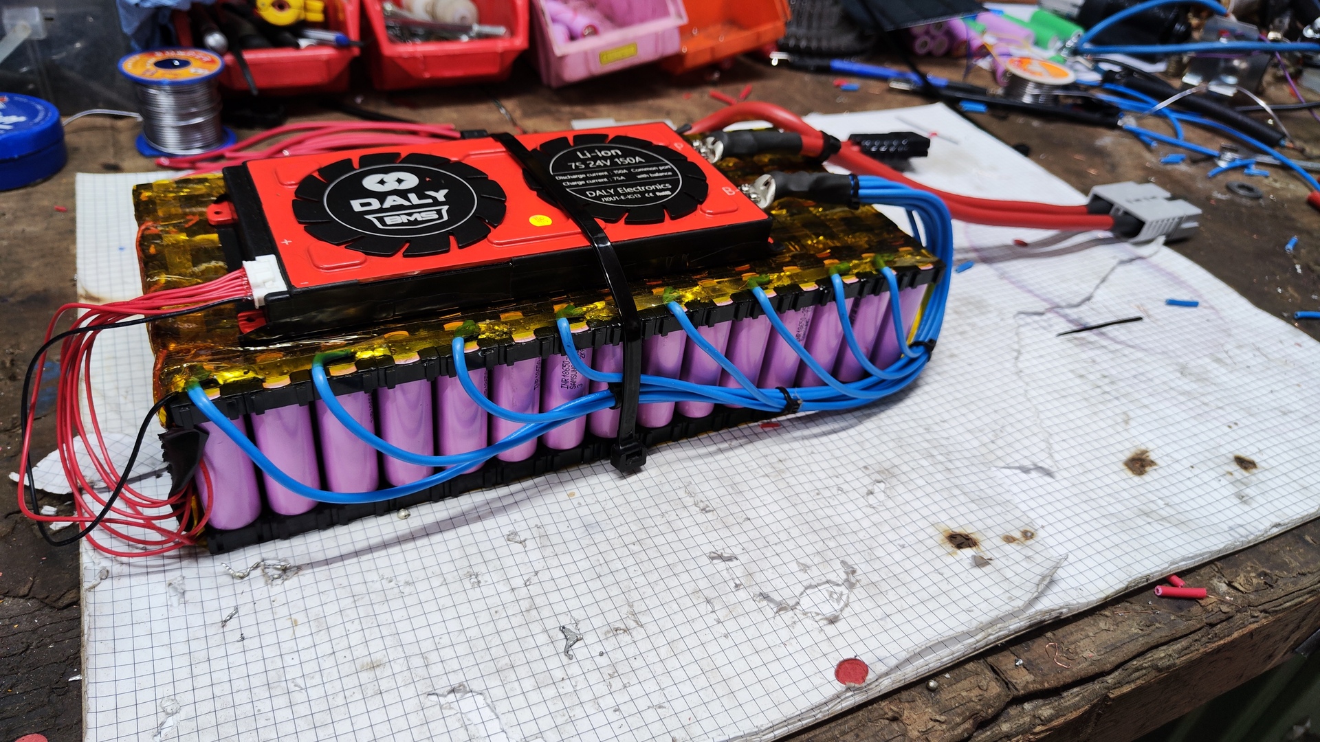
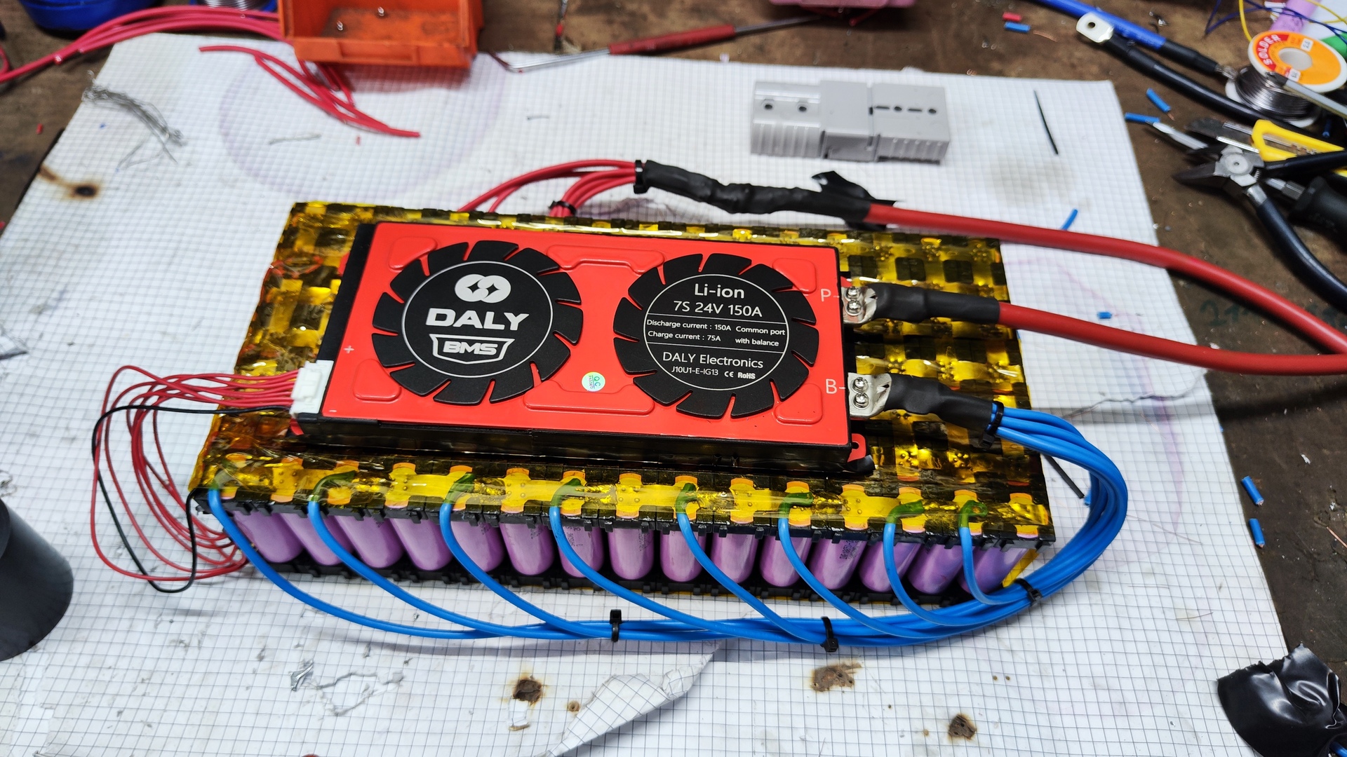
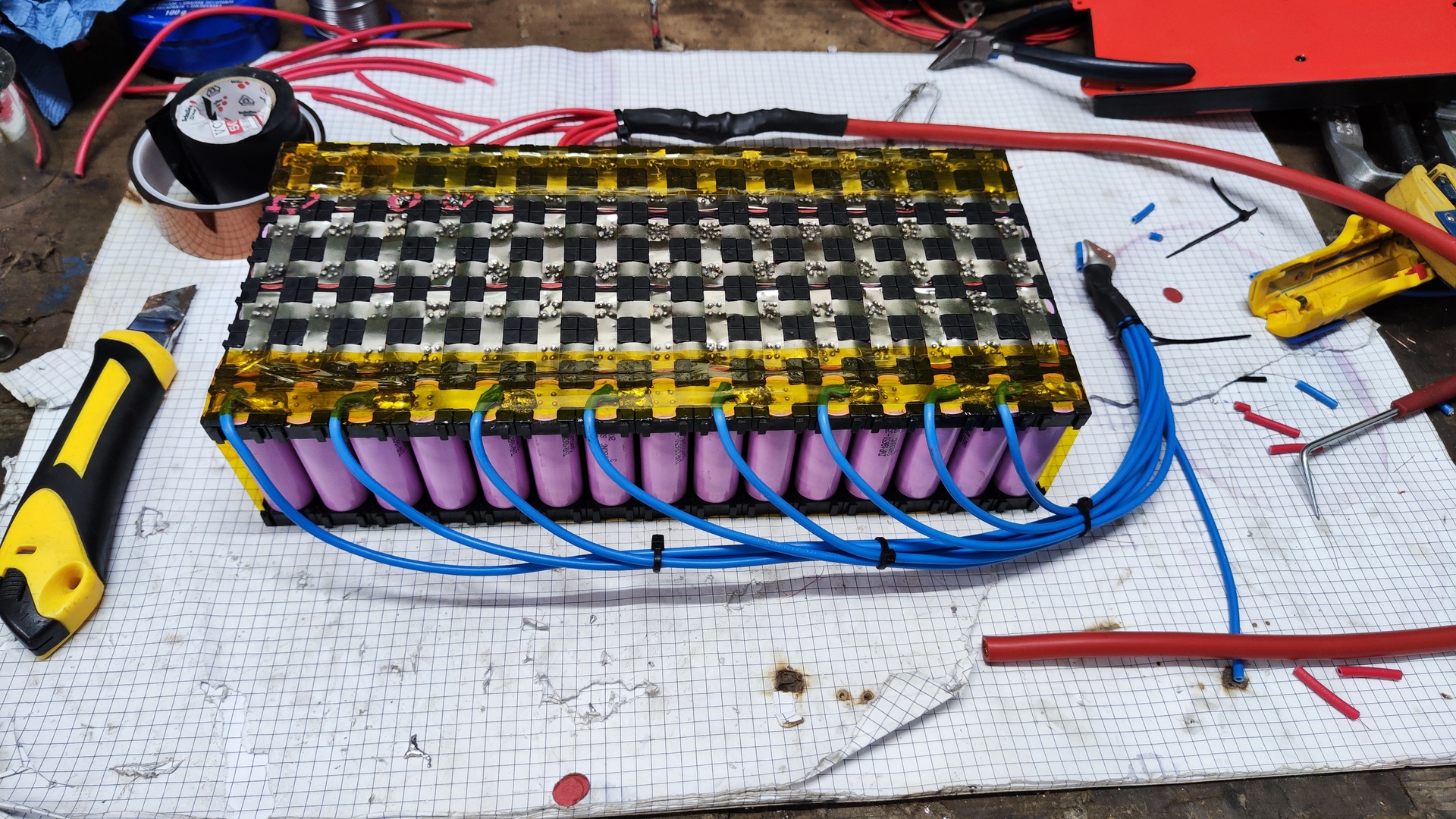
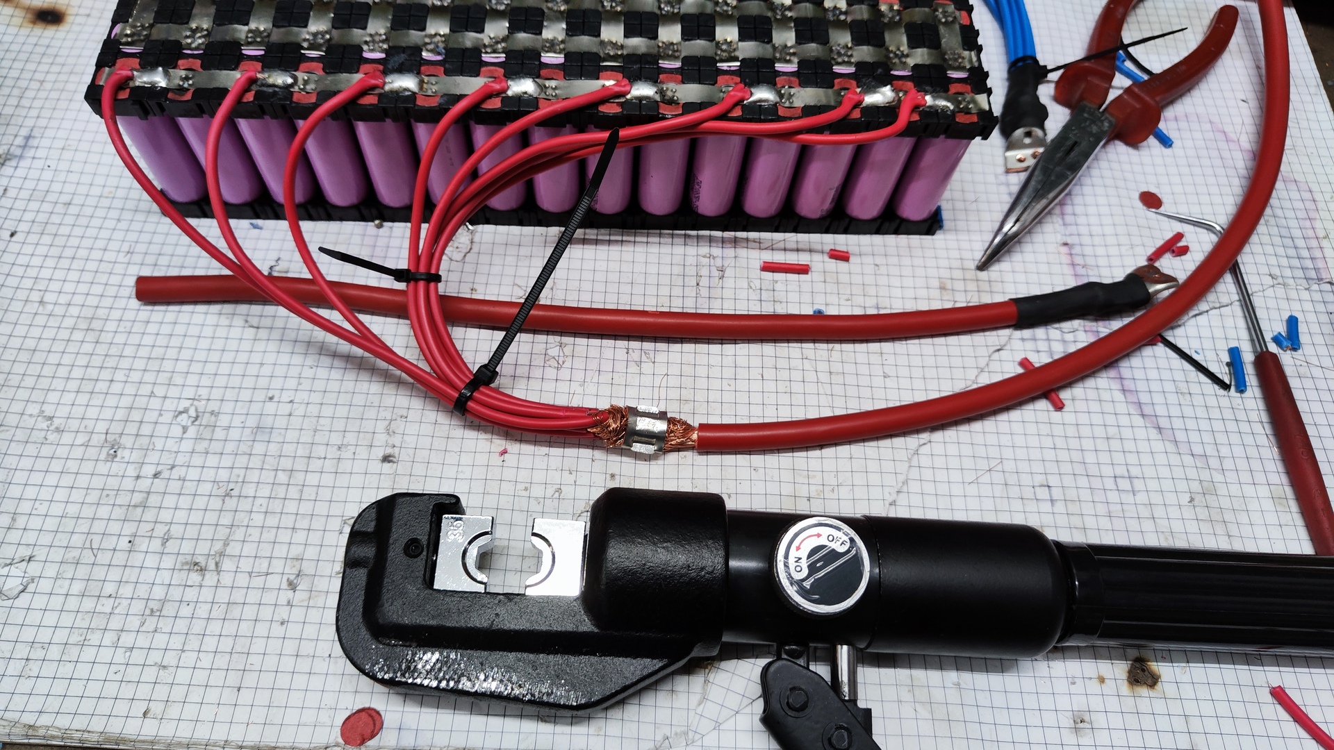
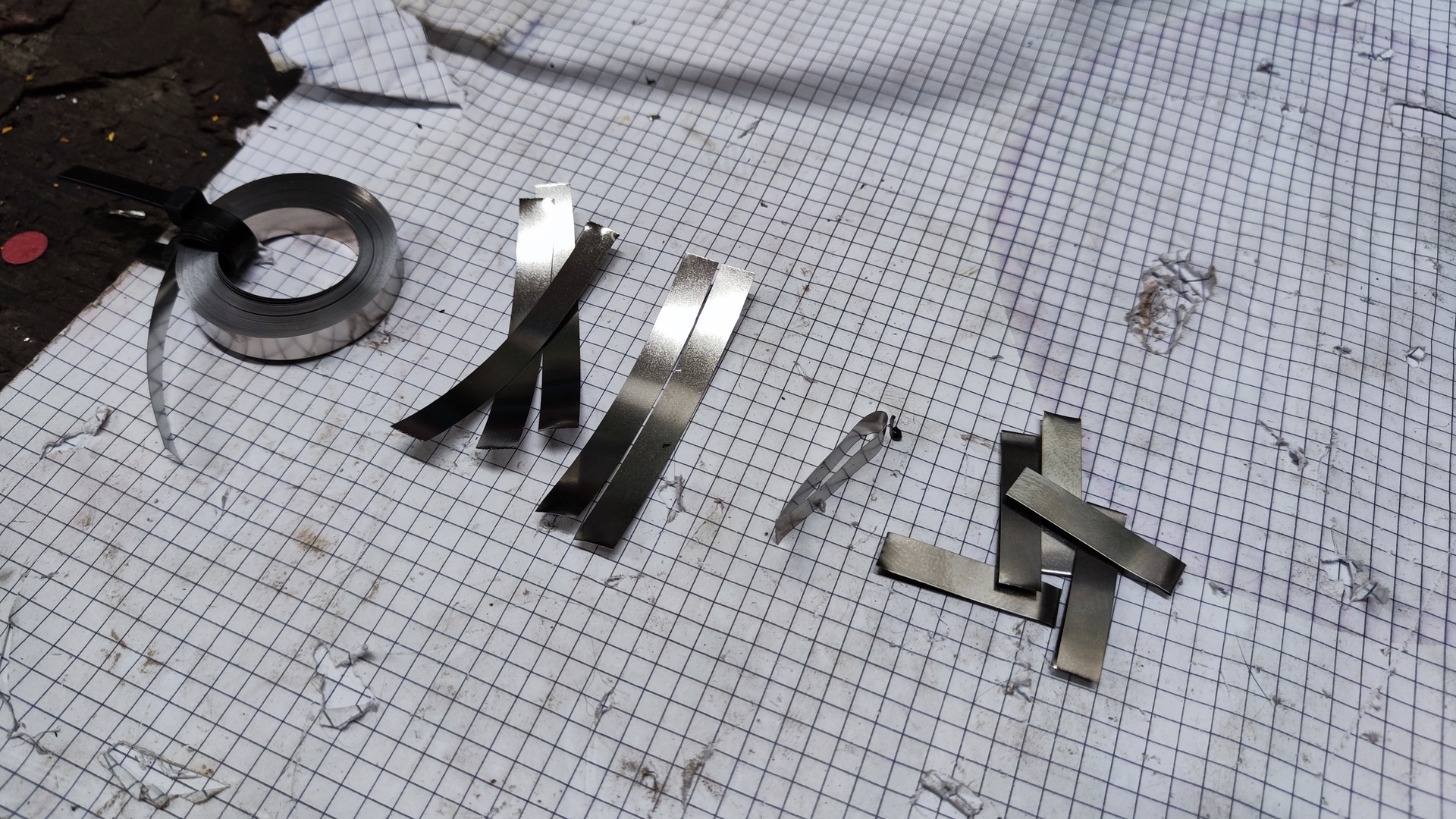
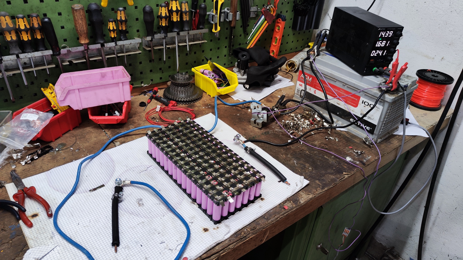
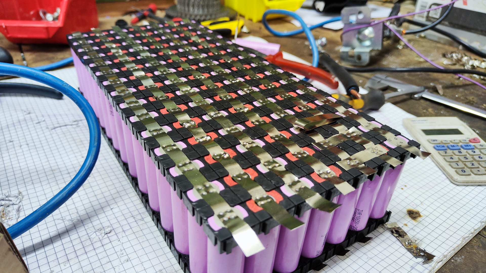
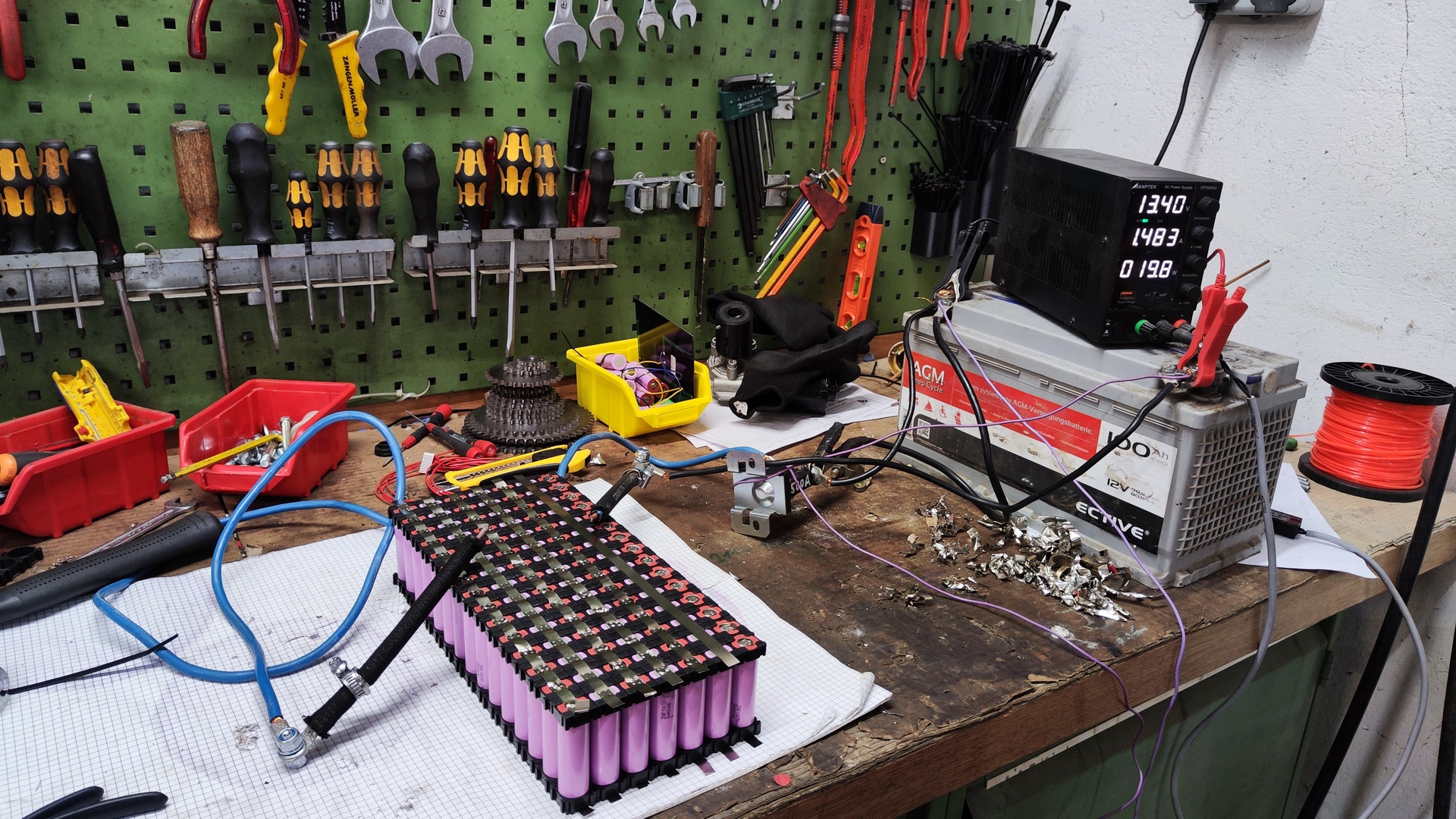
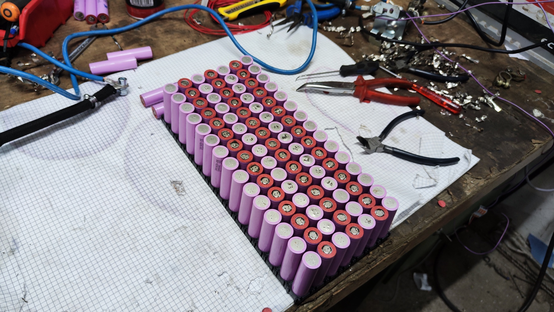
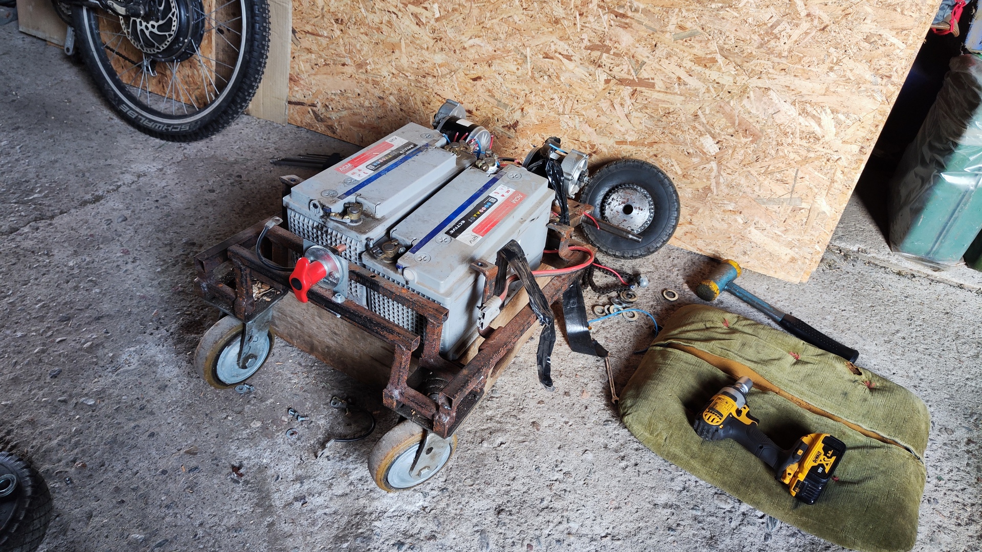
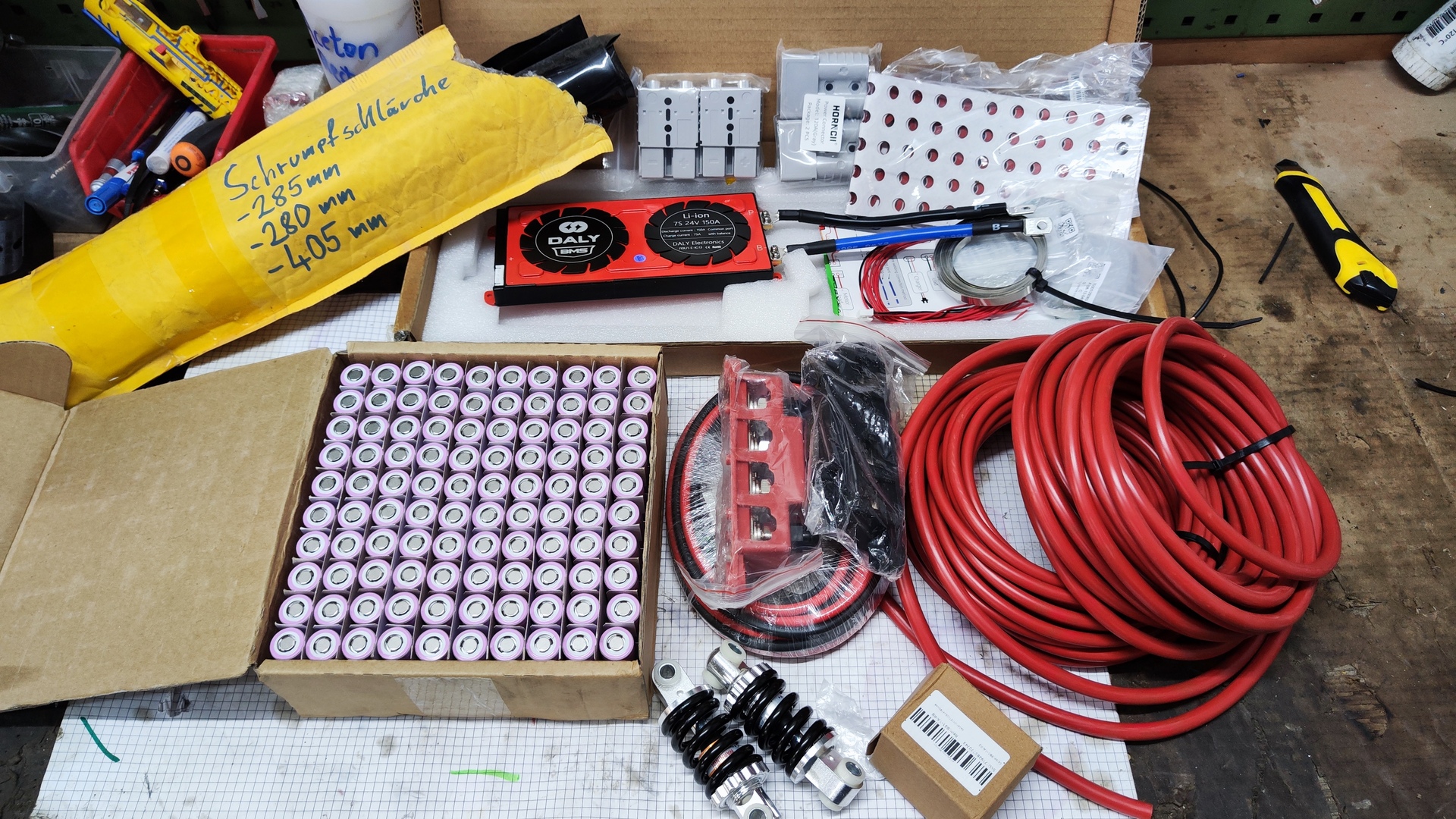
Battery
- Type: Self-made Li-ion
-
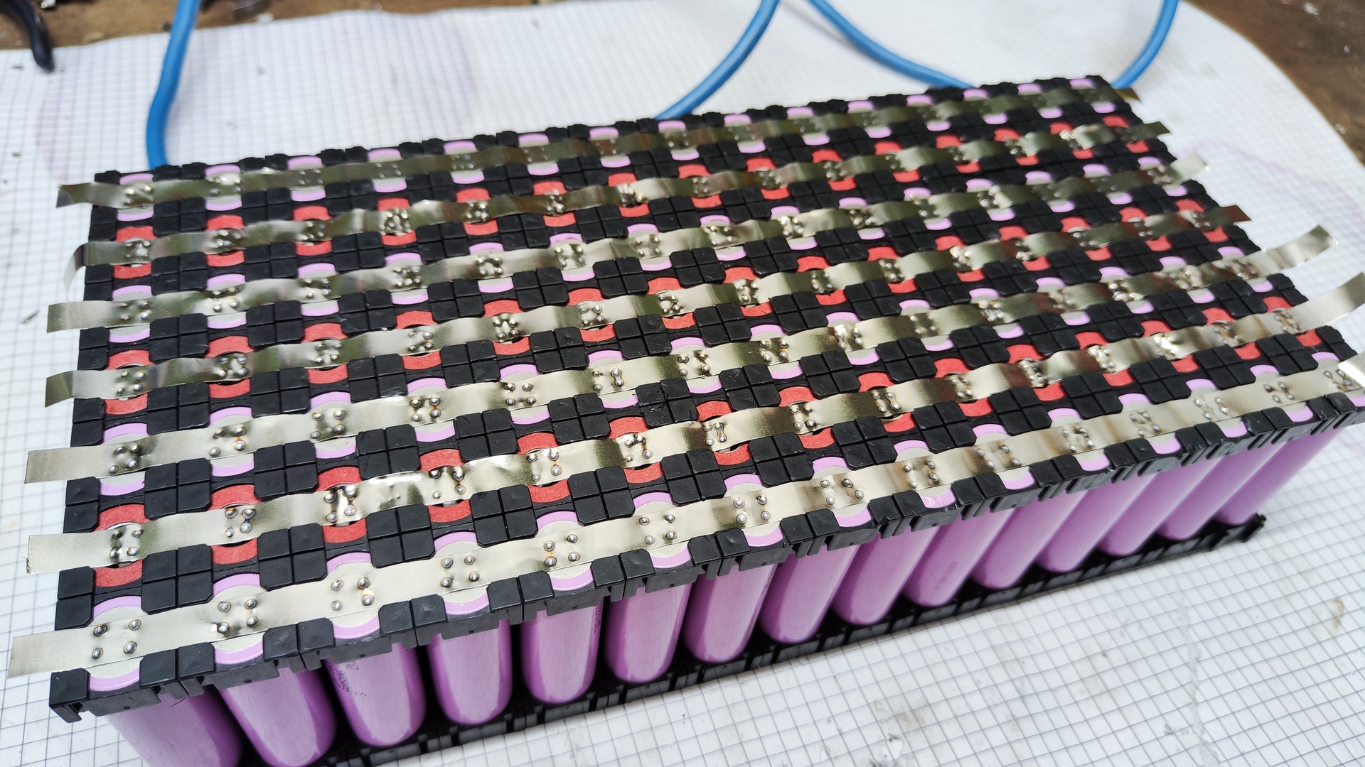
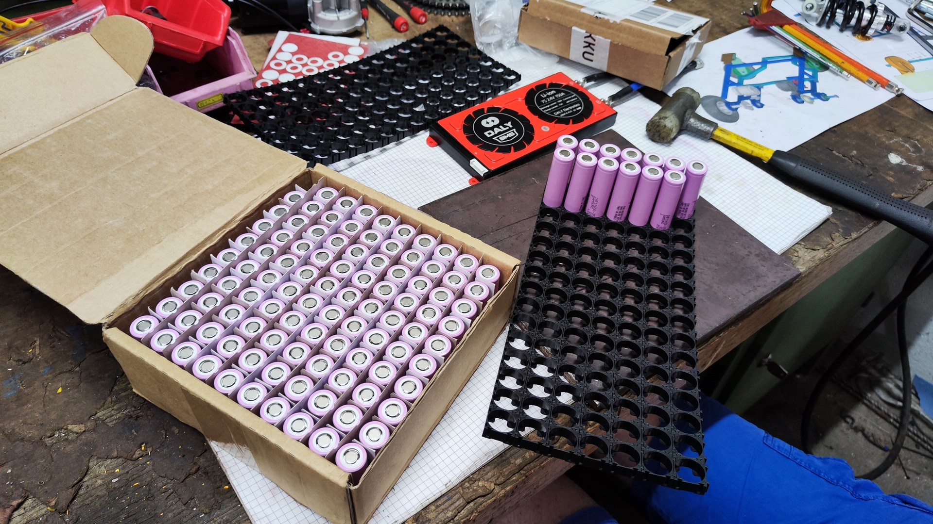
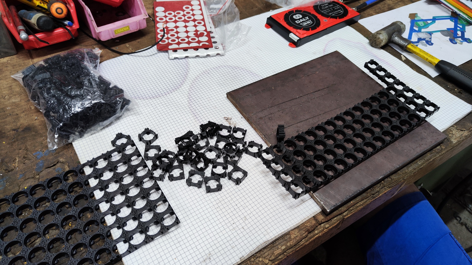
Battery cell:
- Name: Samsung INR18650-35E 3500mAh 3,7V
- Count: 105
- Price: 2.45 EUR per Cell (Ebay)
- Voltage: 25 V (21-29.4 V)
- Capacity: 1.28 kWh (25 V 49.5 Ah)
- Cell connection: 7 series, 15 parallel (7s15p)
-
Battery management system (BMS):
- Max current:
- Discharge: 150 A
- Charge: 75 A
- Type: Li-ion 7S
- Features:
- Over charge protection (4.25 V)
- Over discharge protection (2.7 V)
- Over current protection (260 ±50 A)
- Balancing (30 mA)
- Price: 70 EUR (Aliexpress)
- Max current:
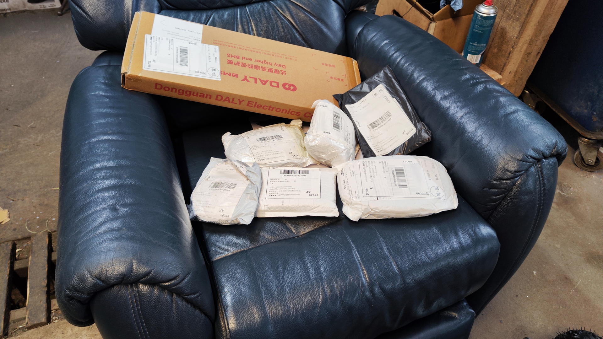
 All battery components included
 Self made battery pack
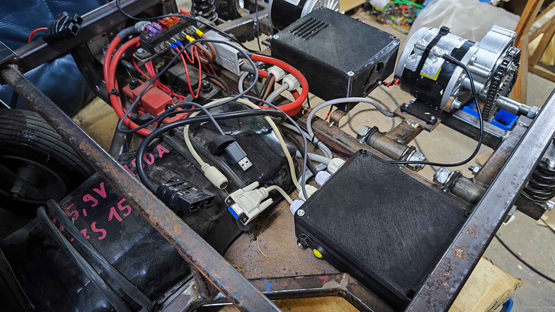
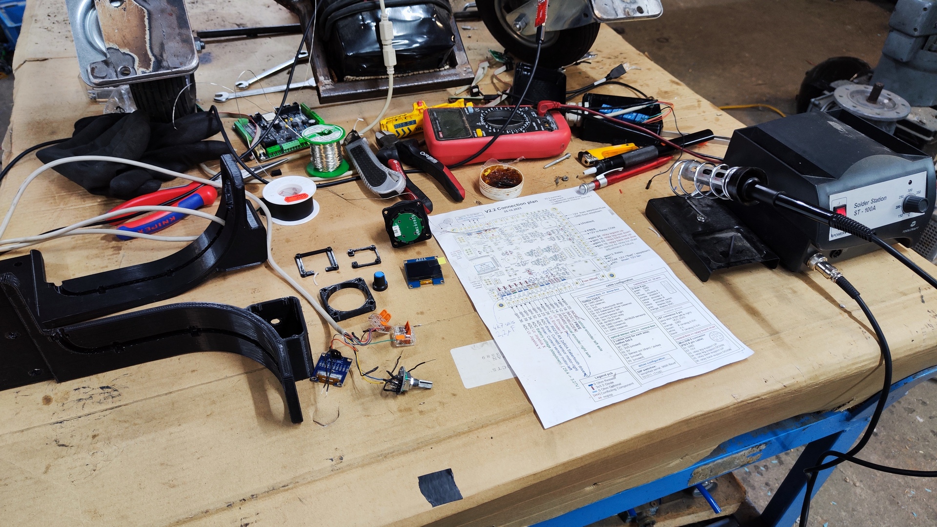
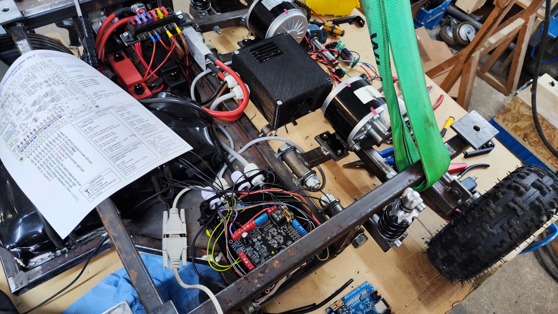
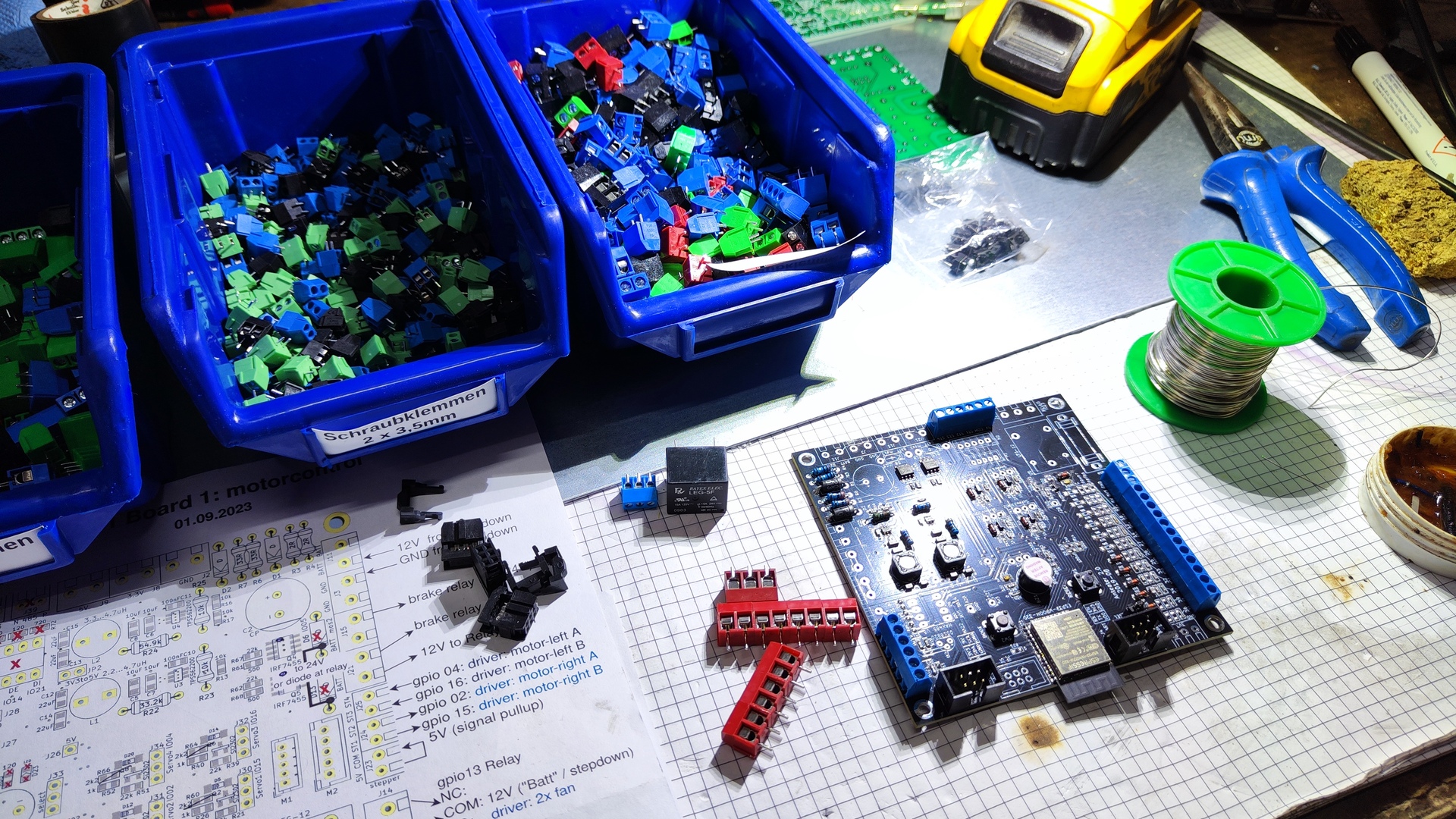
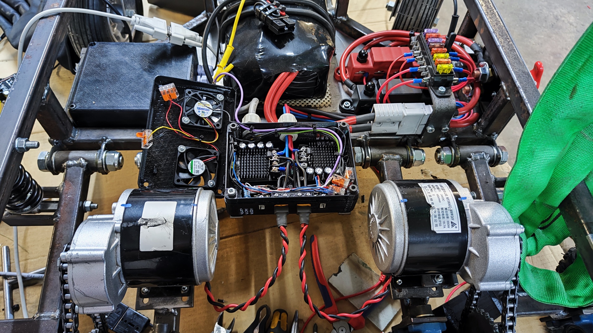
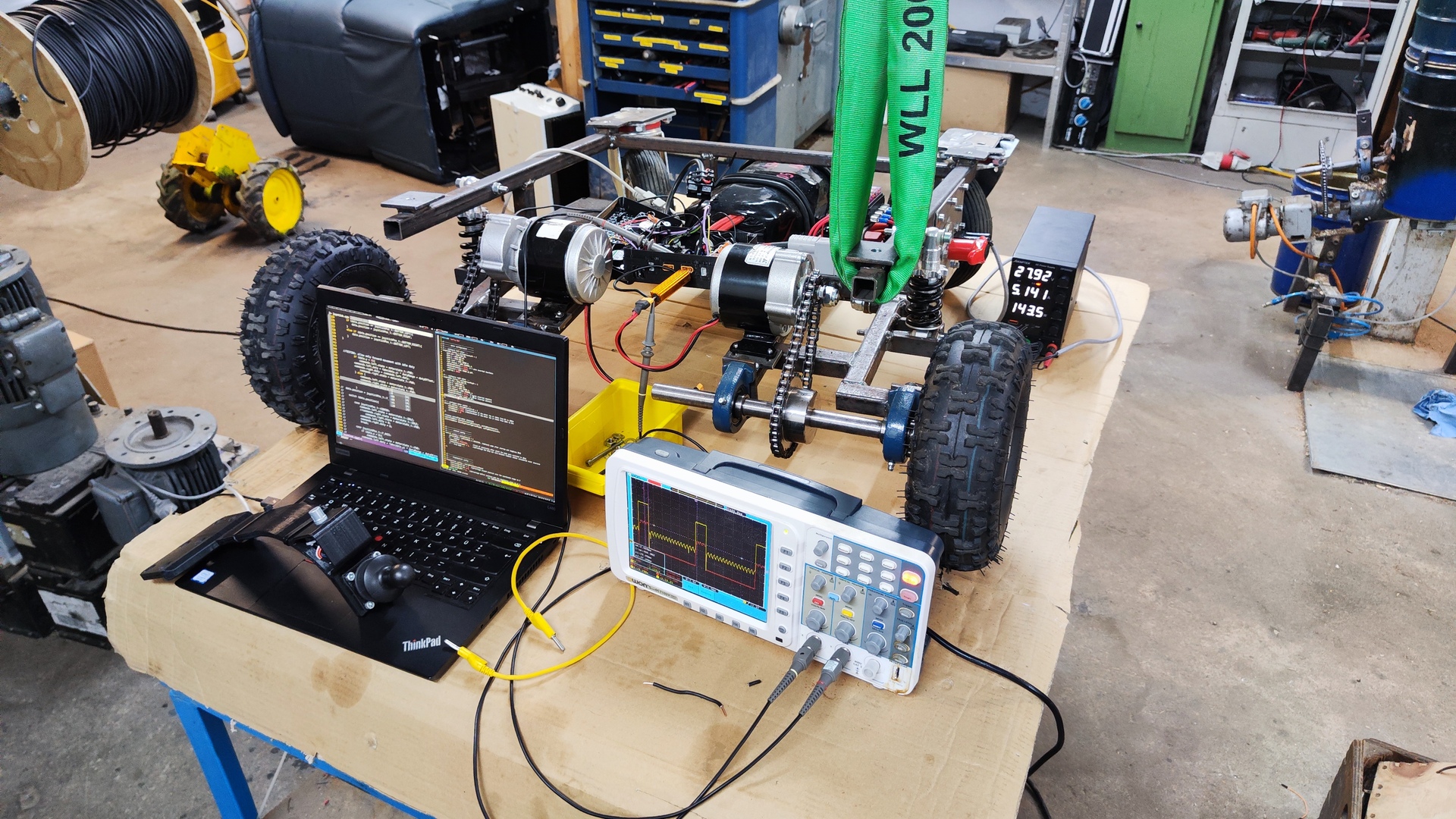
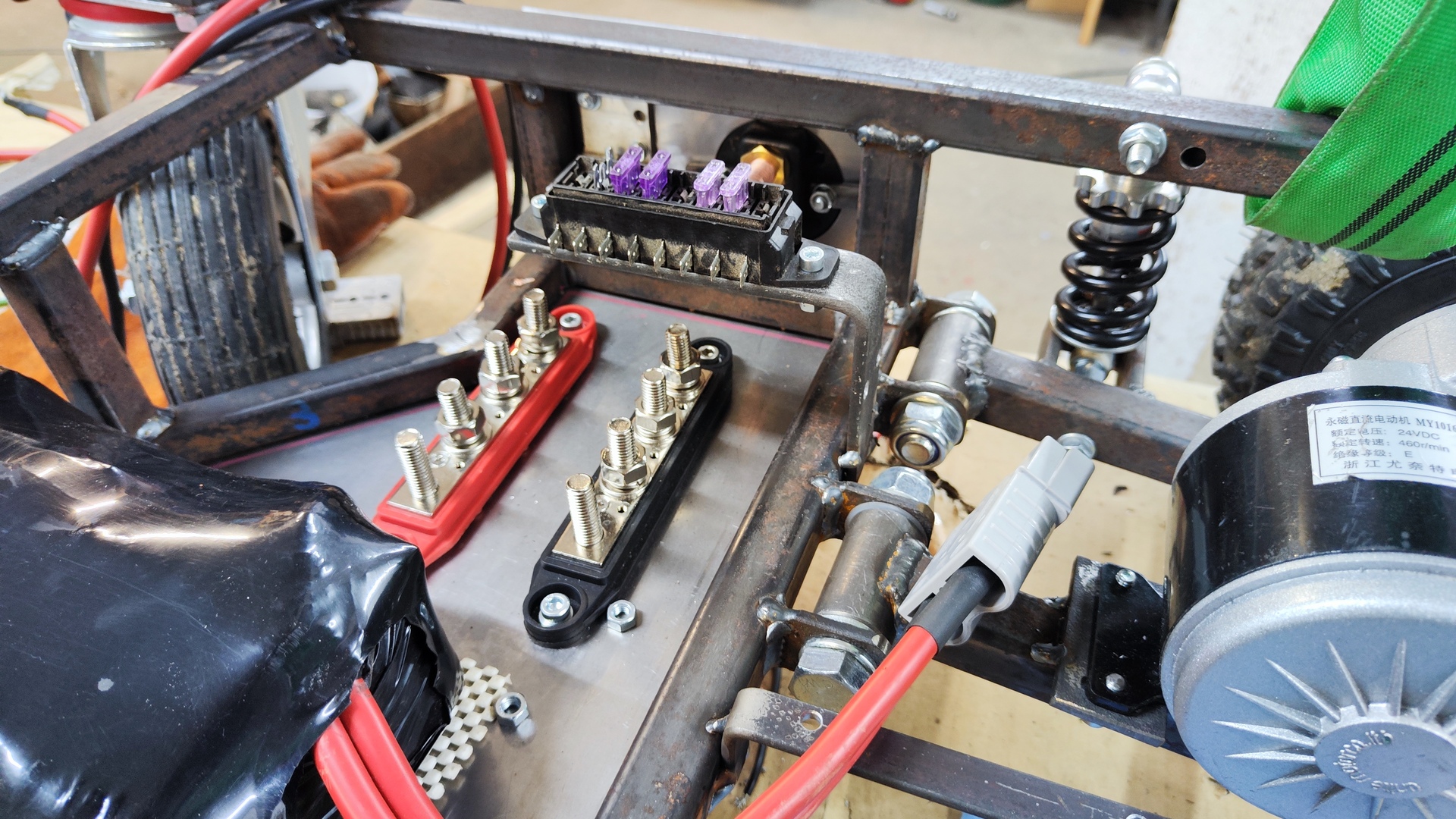
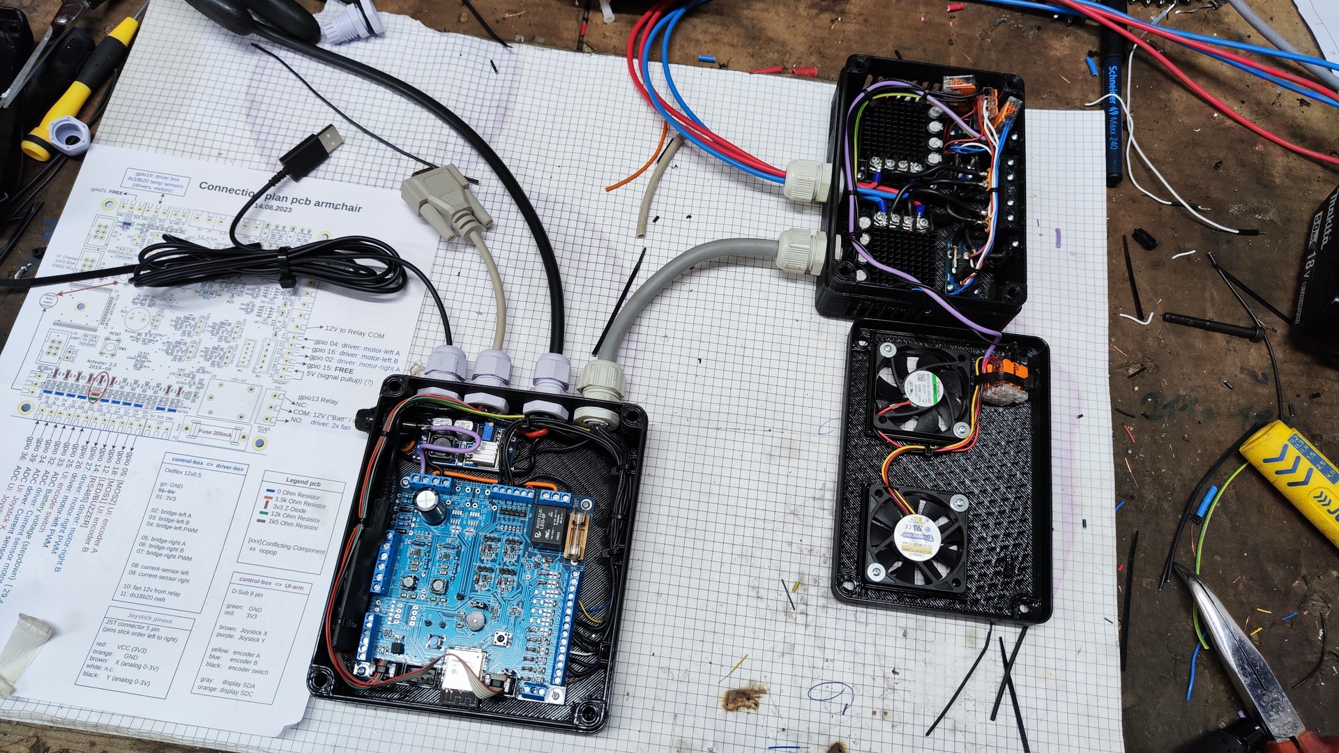
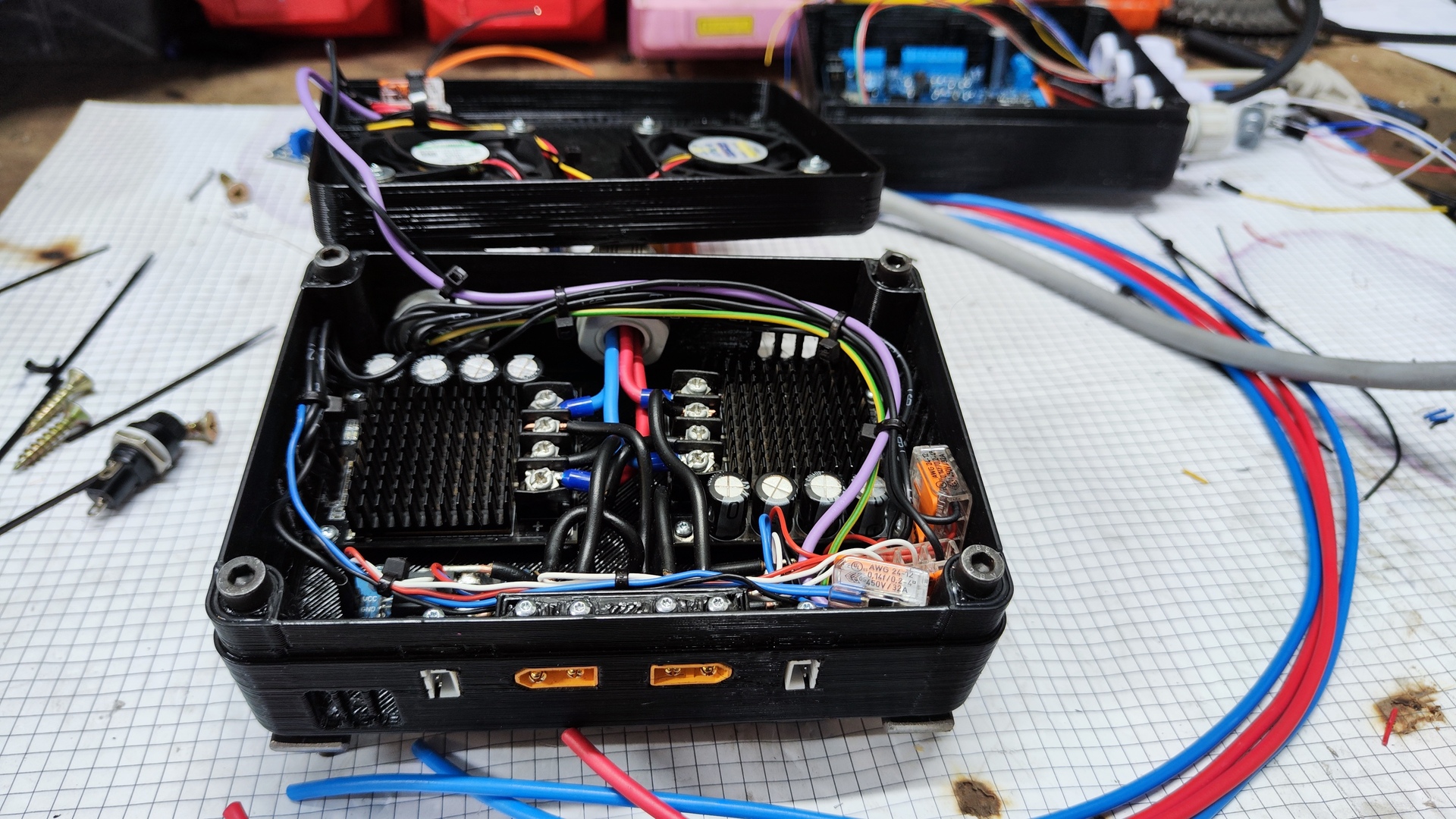
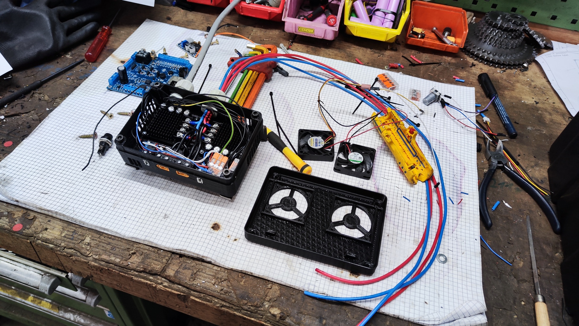
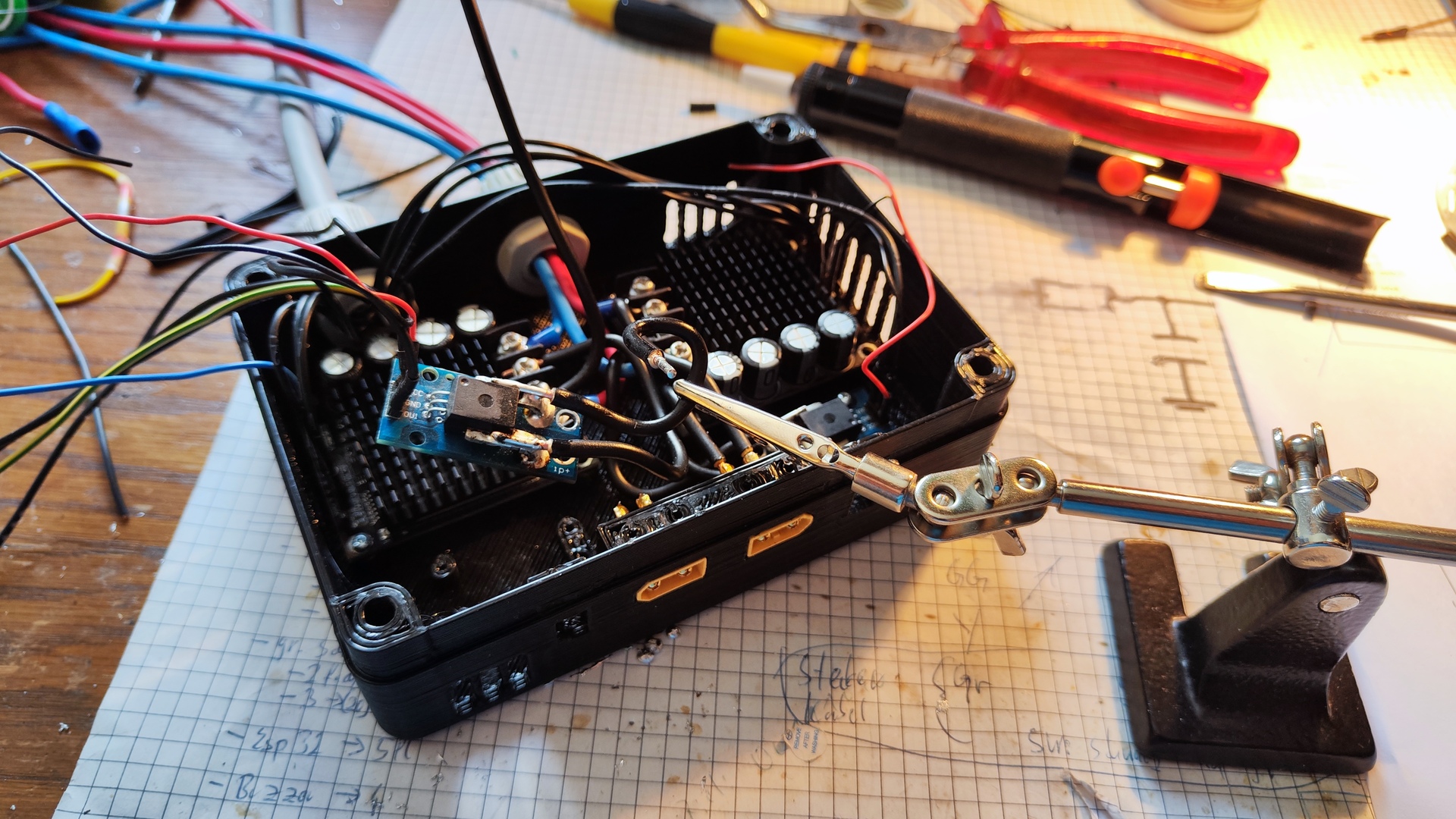
Control System
- Microcontroller: Custom pcb with ESP-32
-
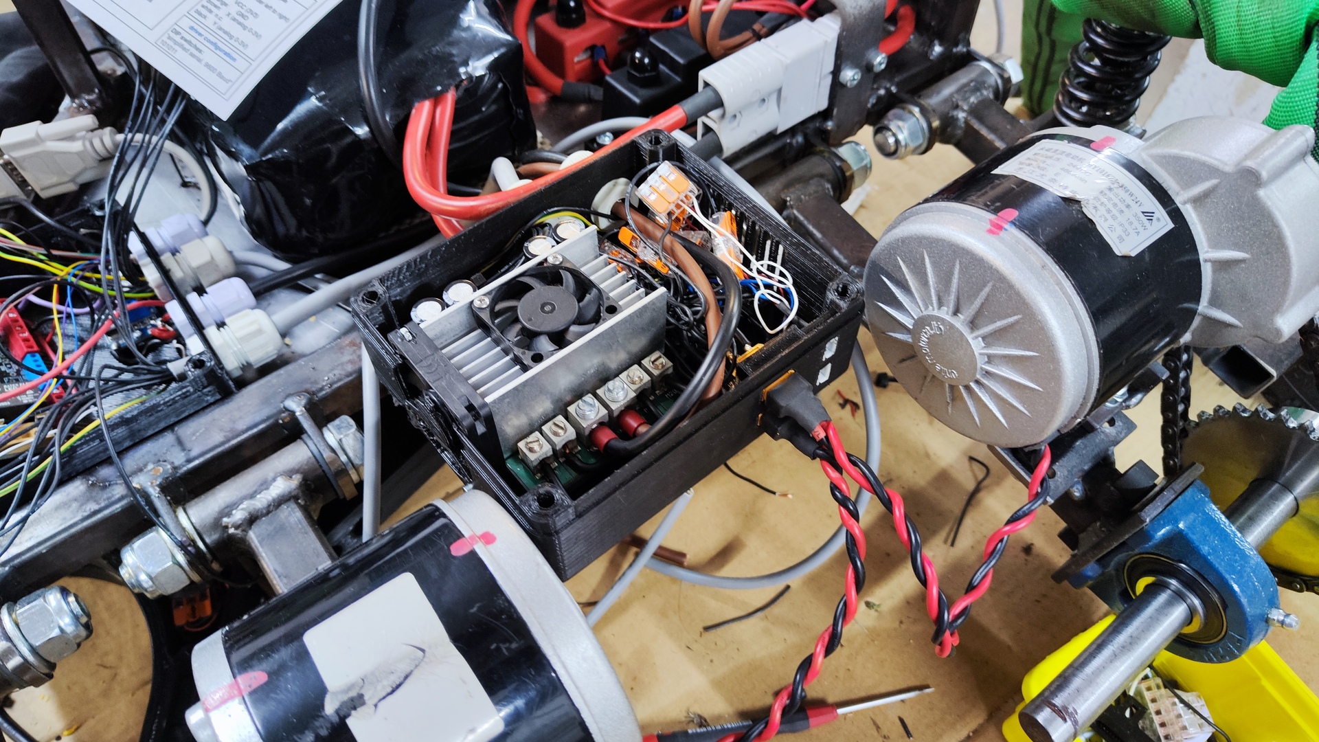
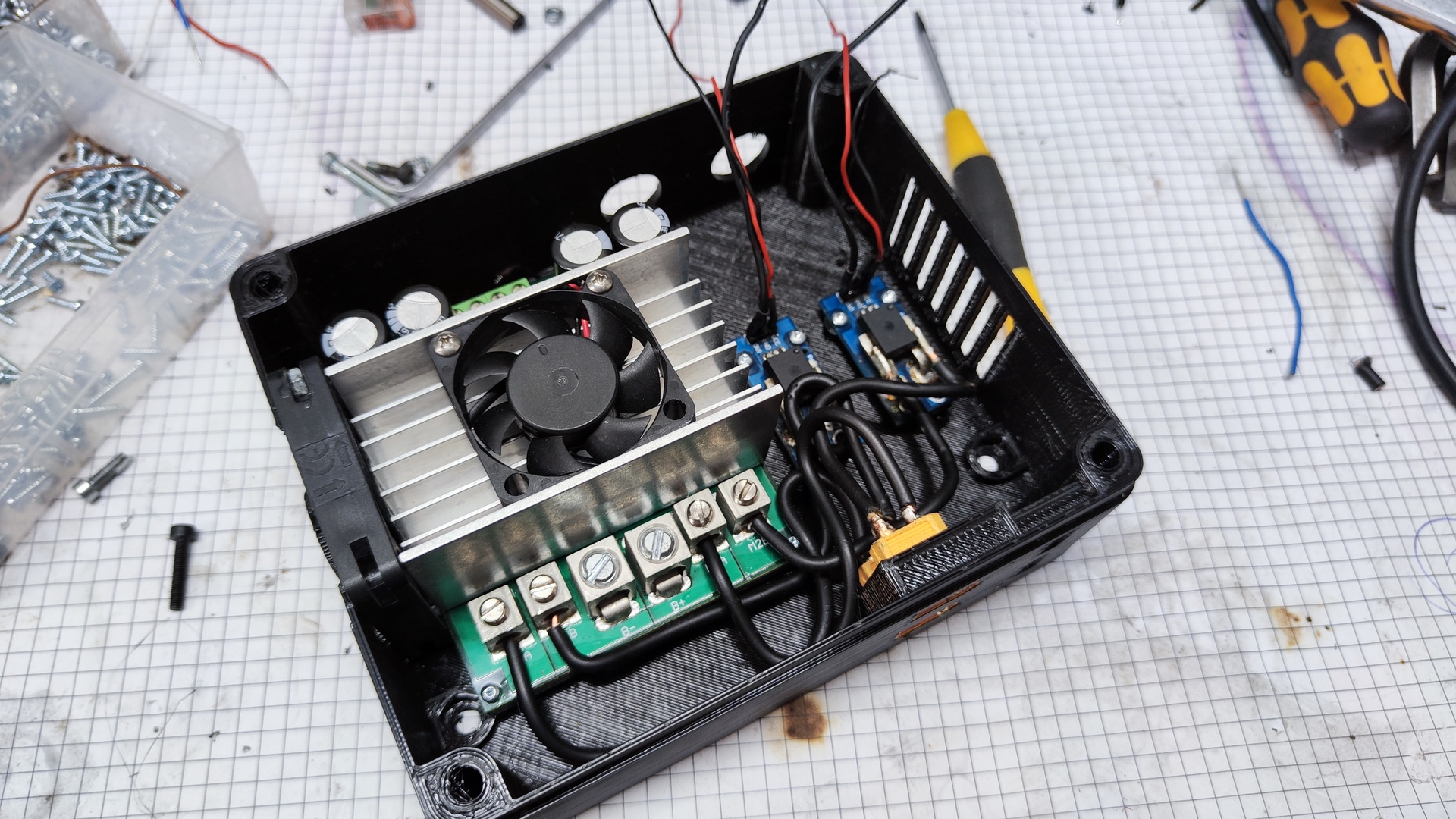
Motor driver:
- Brand: Sabertooth
- Voltage range: 6-30 V
- Current:
- Continuous: 2x60 A
- Peak: 2x120A
- PWM frequency: 32 kHz
- Interface: Serial (TTL RS232)
-
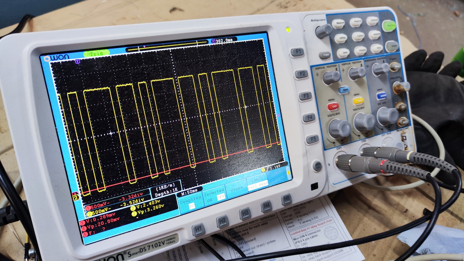
Sensors:
- Speed measurement: 2x photoelectric sensor + custom encoder disk
- Current measurement: 2x analog hall-sensor
- Temperature sensors: ds18b20 (motors and driver)
-
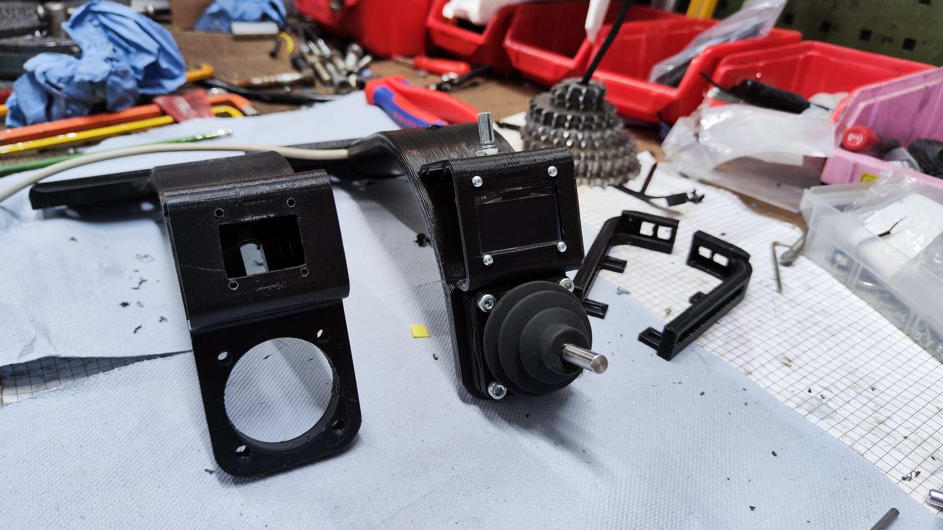
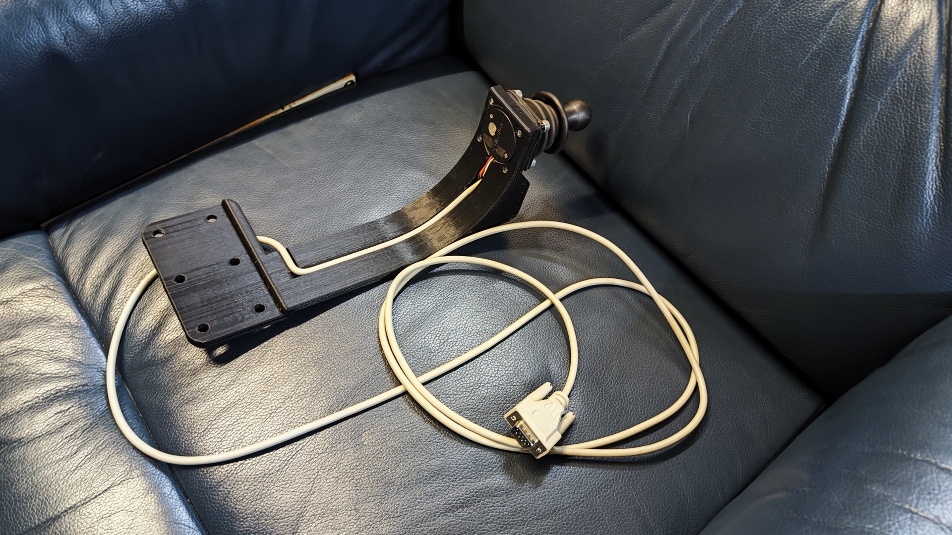
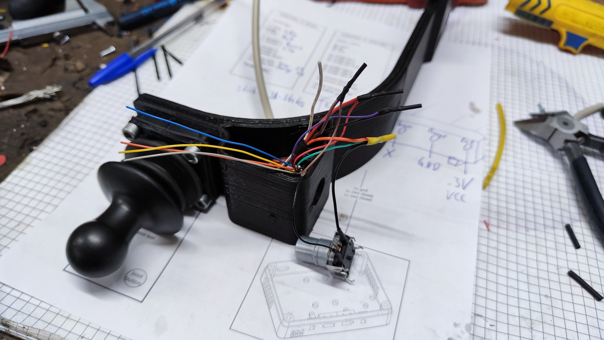
User interface:
- Analog joystick
- 64x128 OLED display
- Rotary encoder
- Button
- Wireless control: WiFi + React web-app
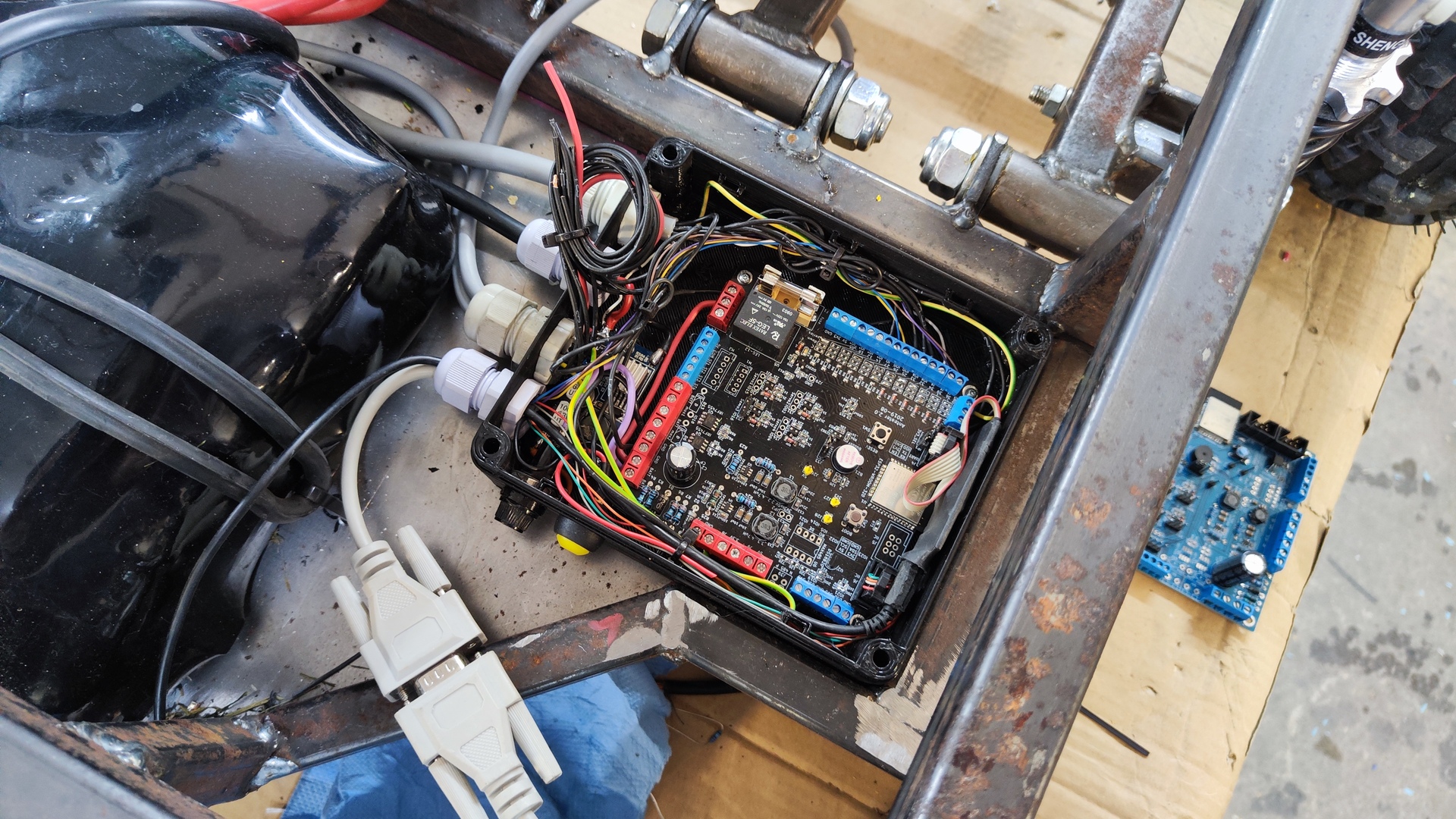
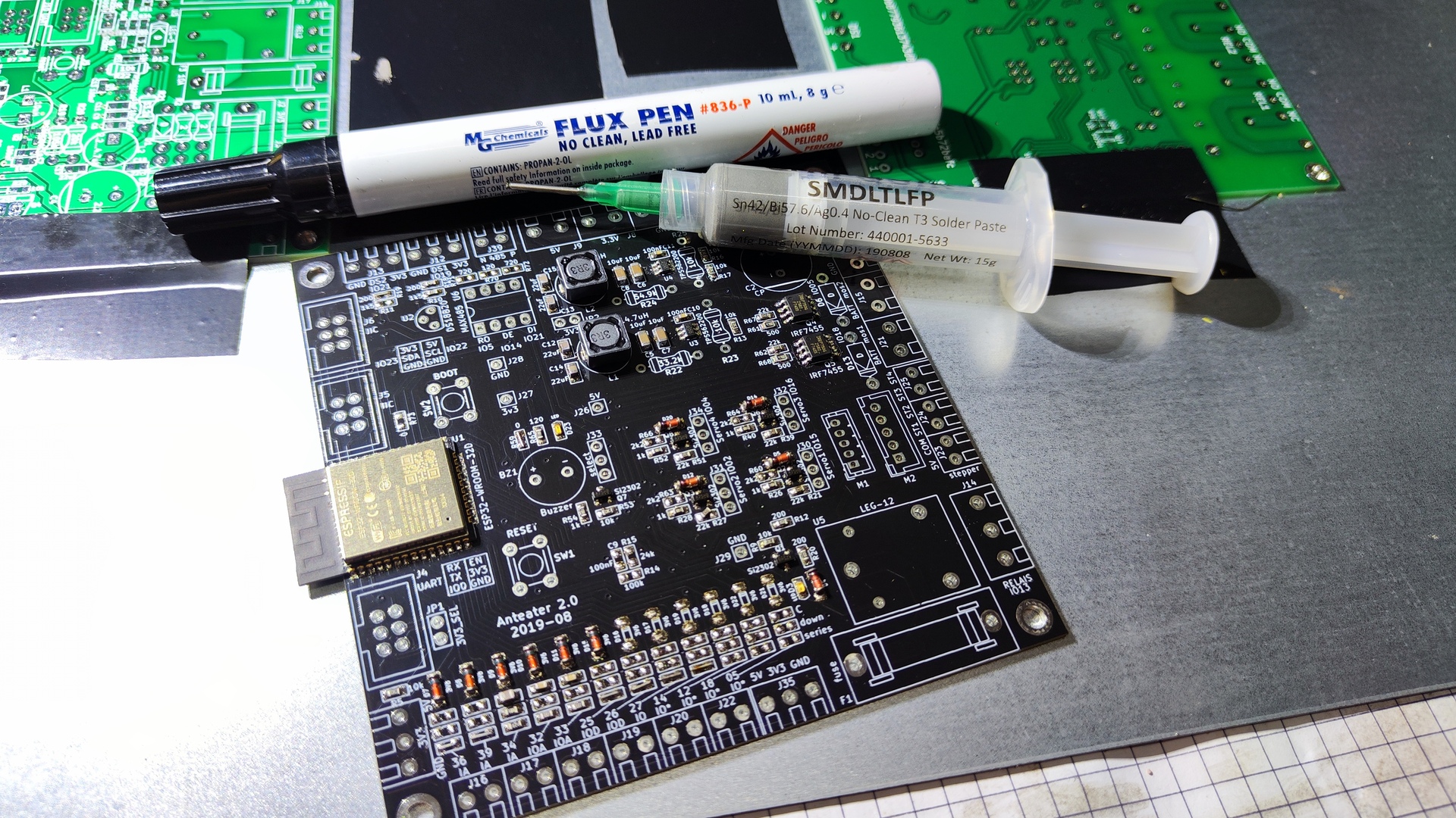
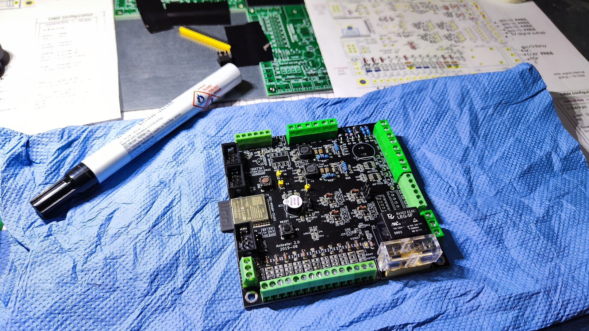
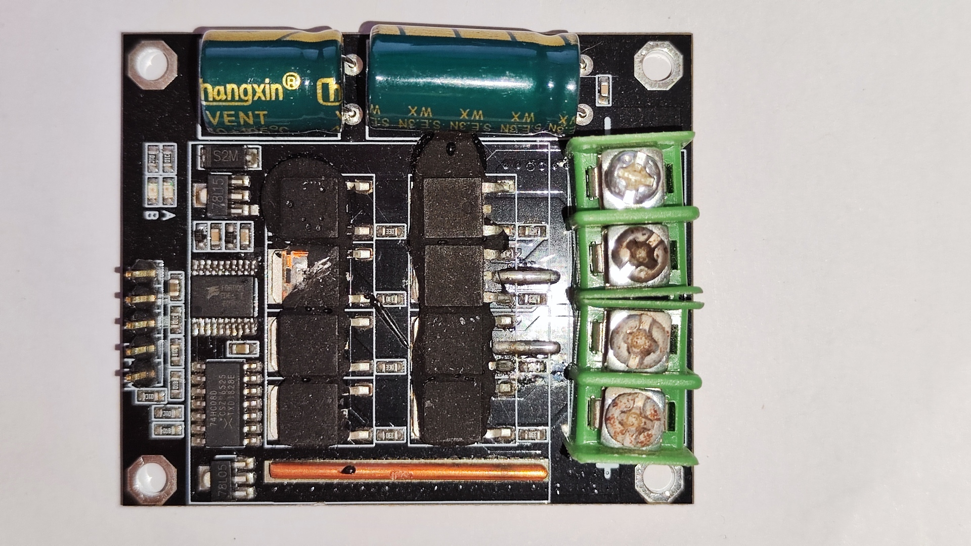
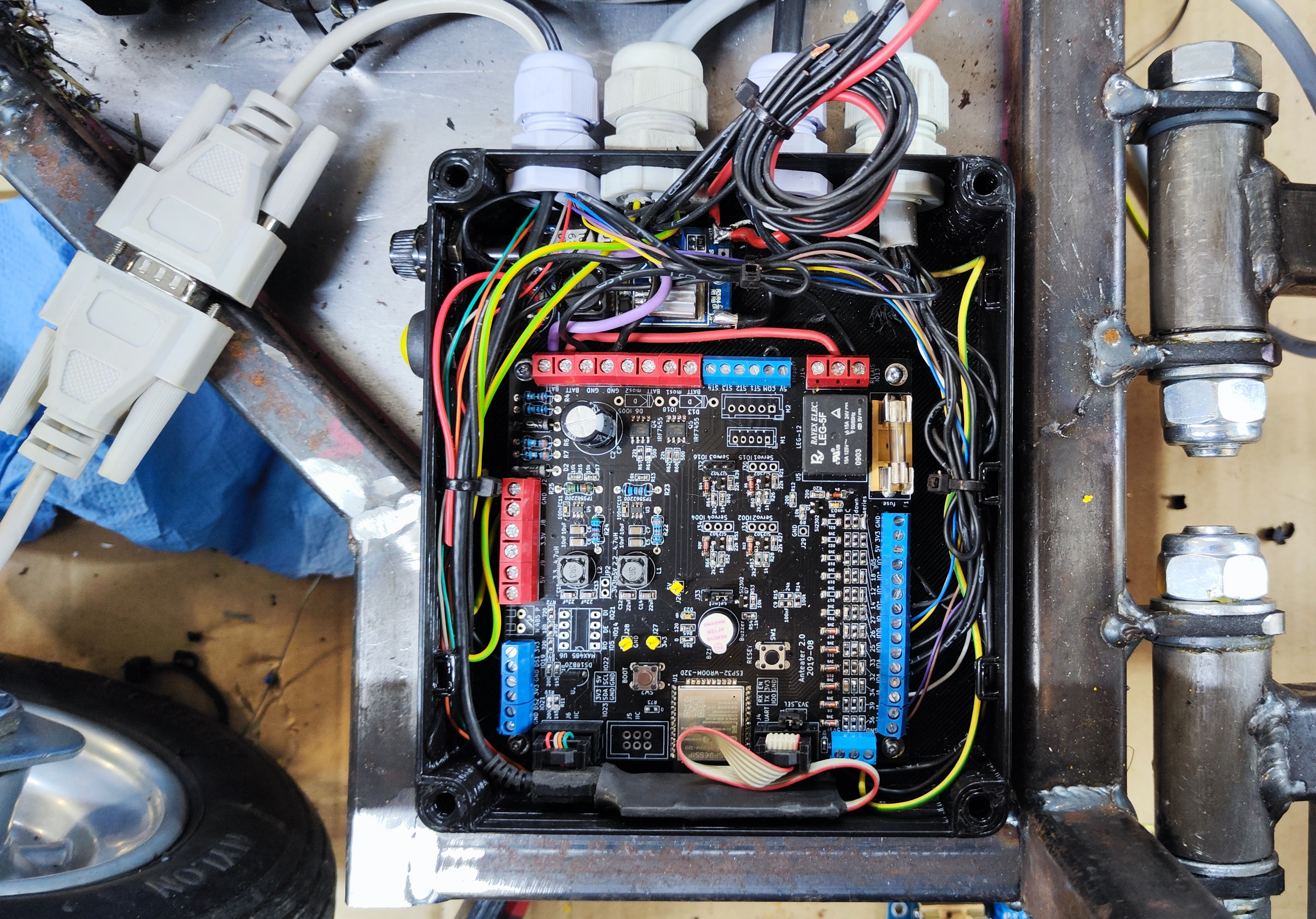 Control board
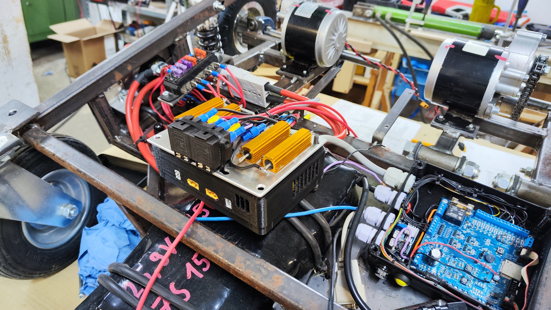
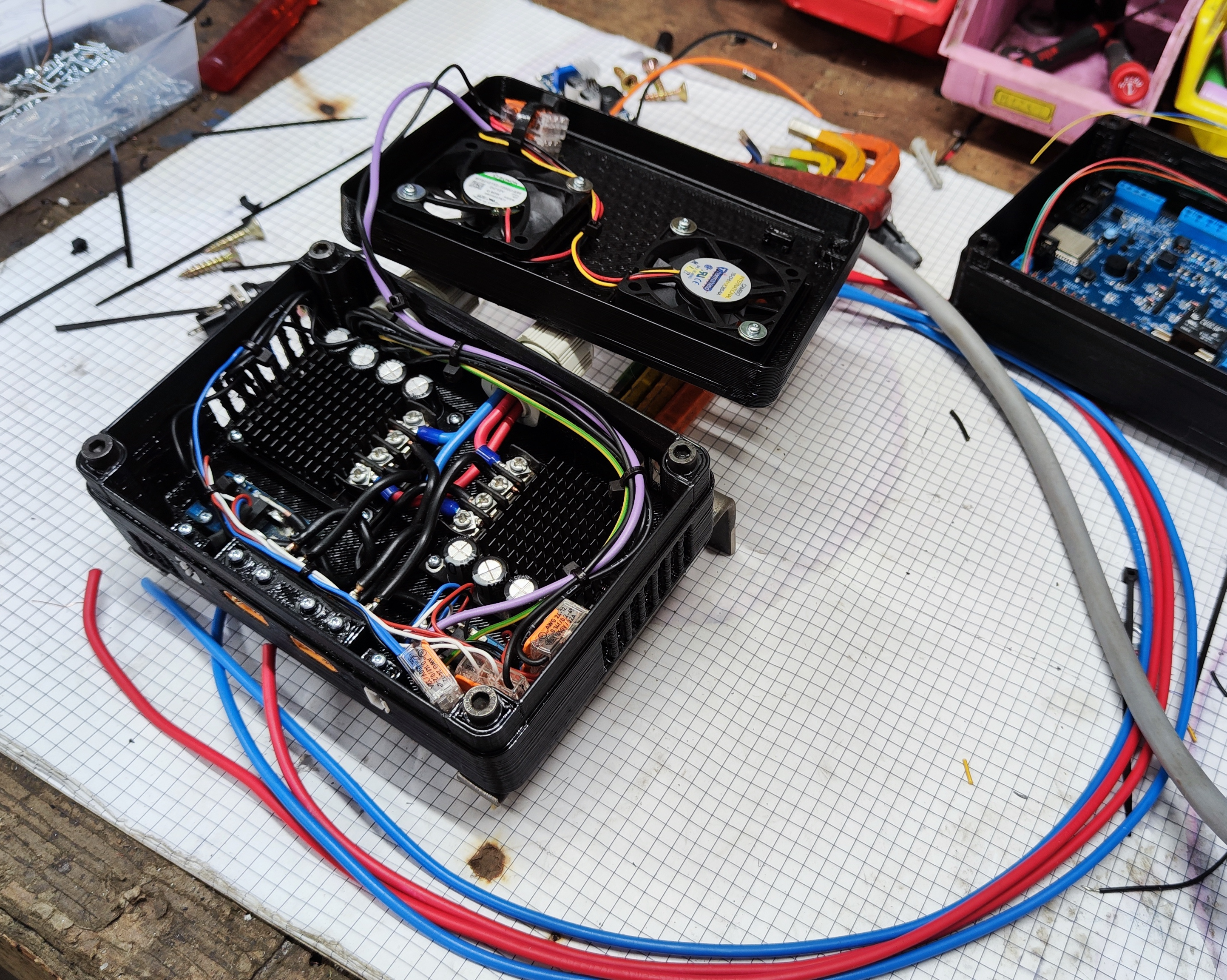
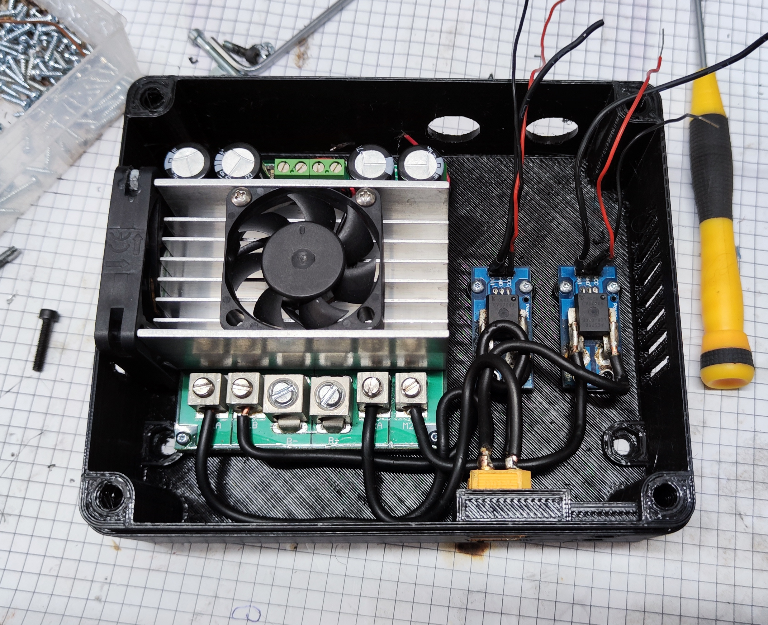 Box with motor driver and current-sensors
Electrical overview
All electrical aspects were planned in the following document:


Complete Document
Firmware
The firmware for the ESP32 microcontroller was created using the following components:
- C++ (Programming language)
- ESP-IDF (Development framework)
- diagrams.net (Flowcharts)
- Git (Version control)
The repository with the source code and all relevant documents is available on GitHub
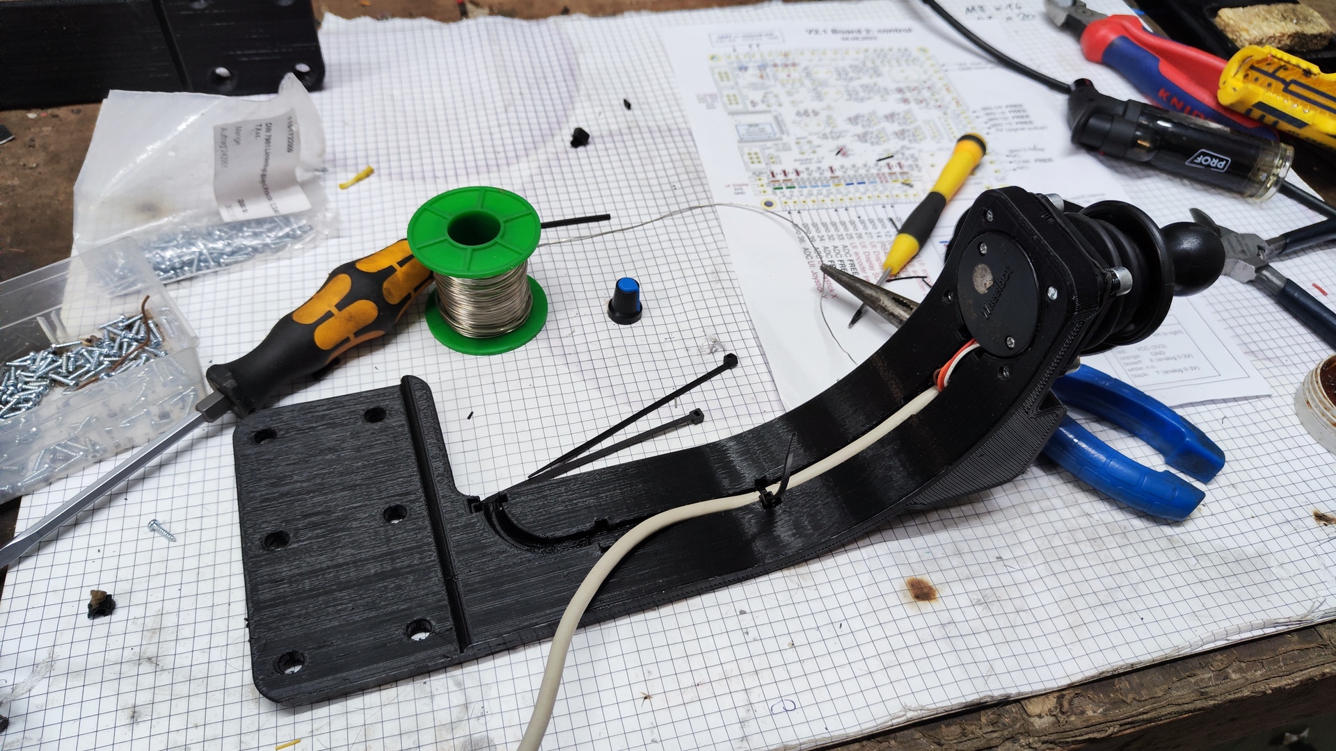
 Joystick mapping
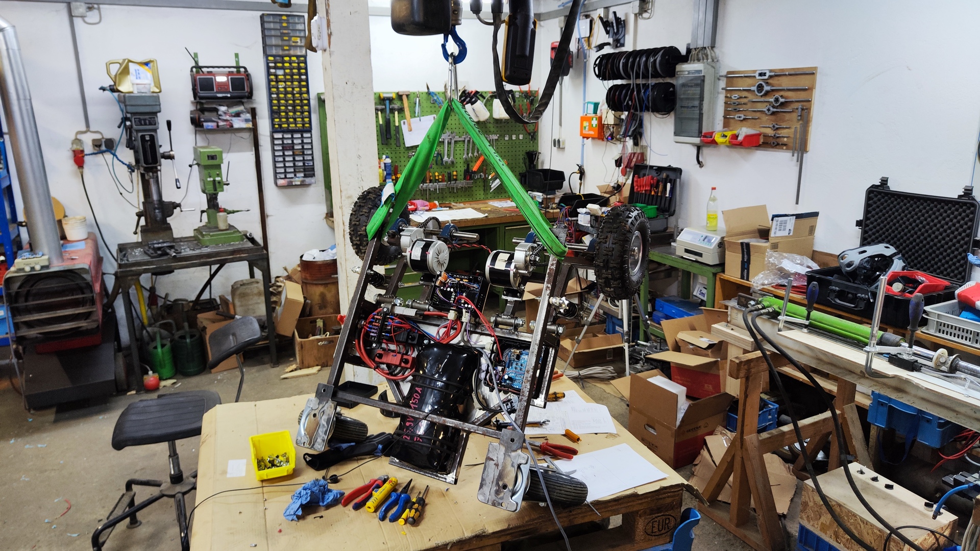
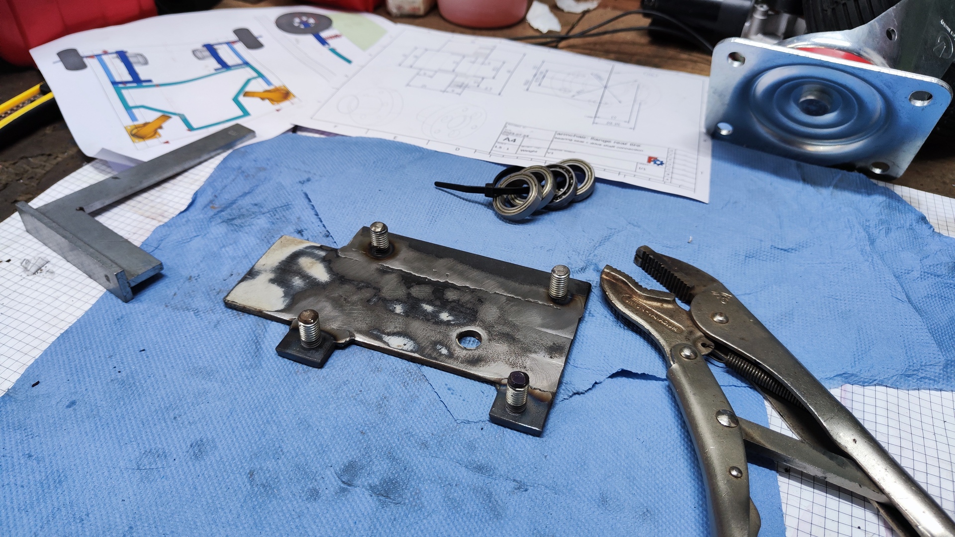
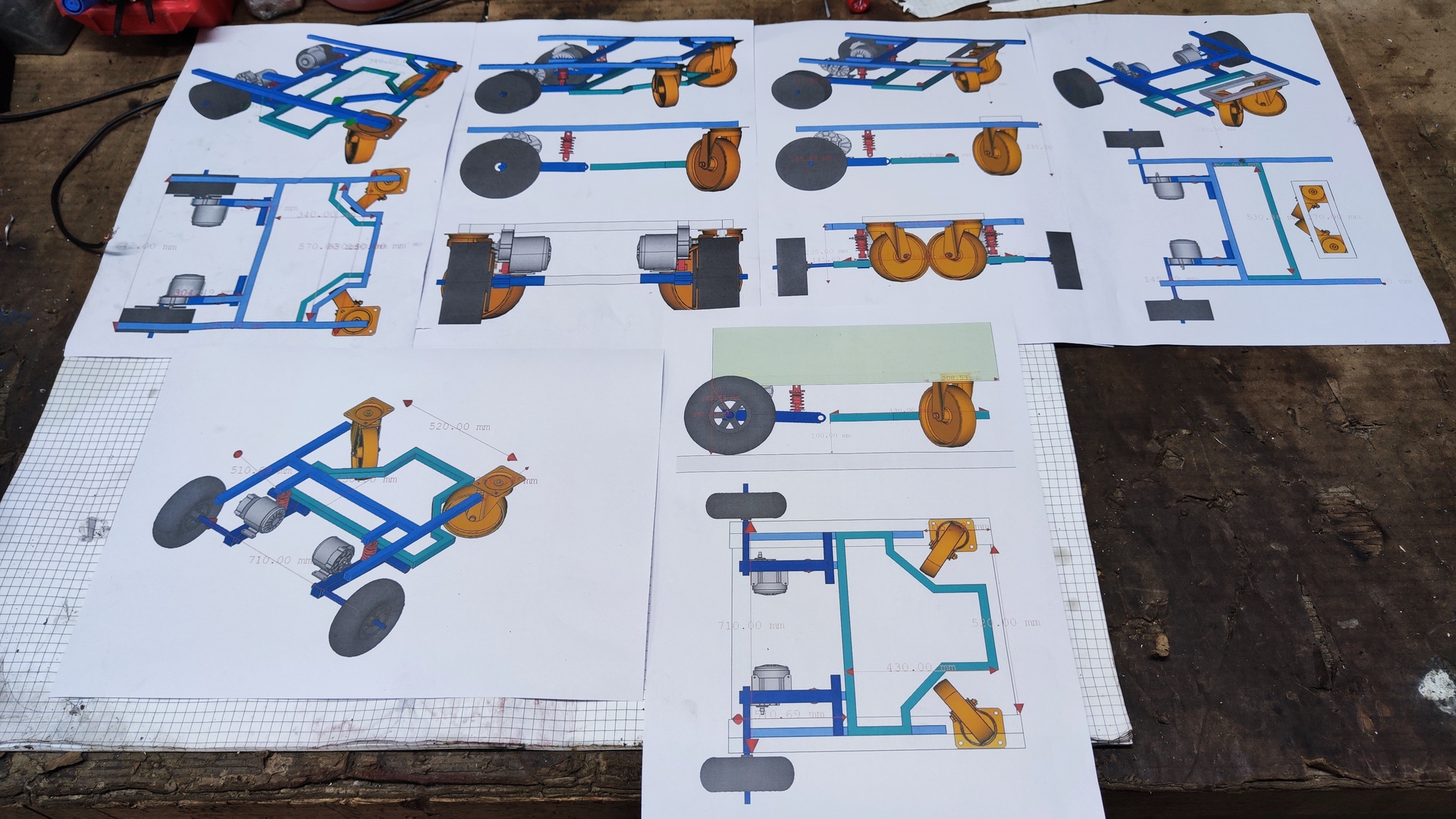
3D-Model
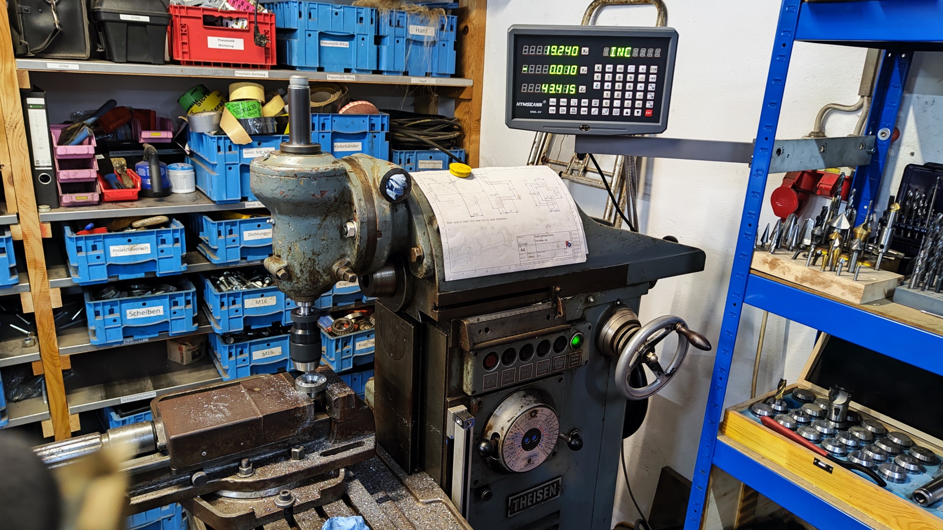
The entire build was planned in detail using CAD software. The model below showcases all the constructed and 3D-printed components:
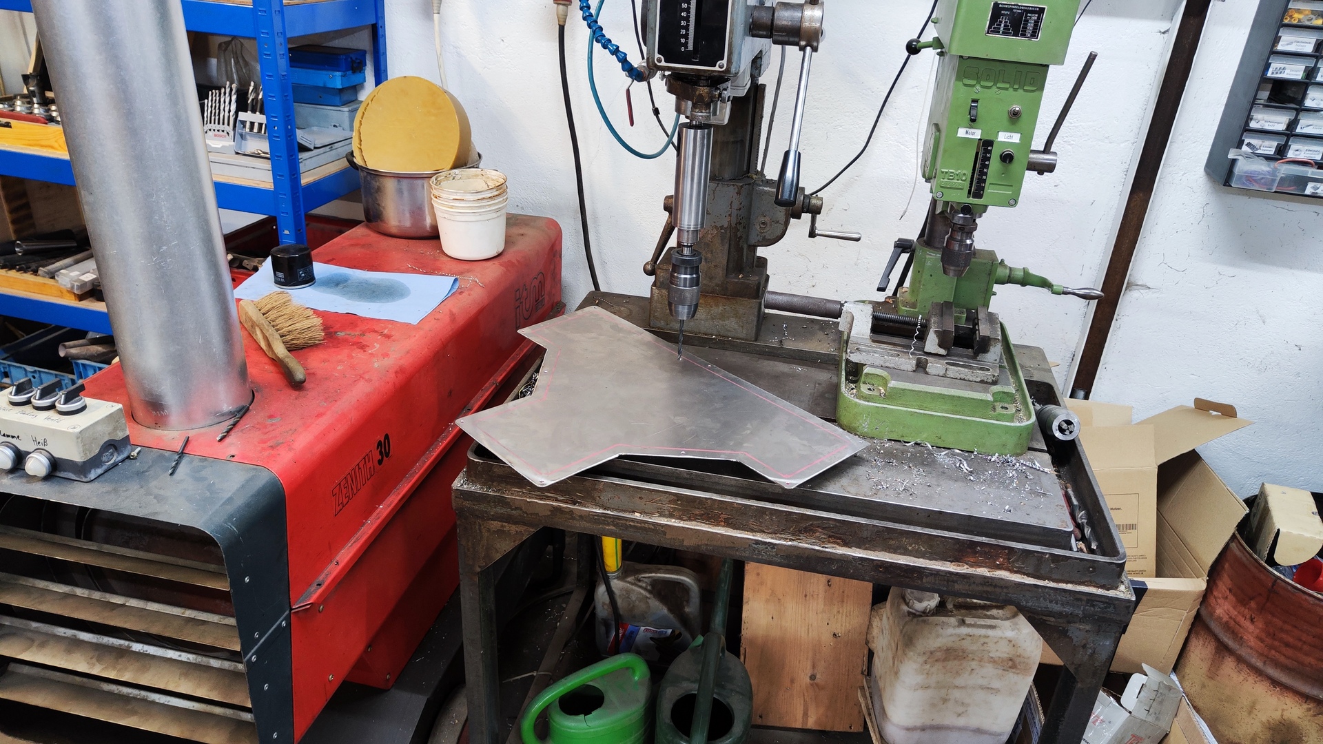
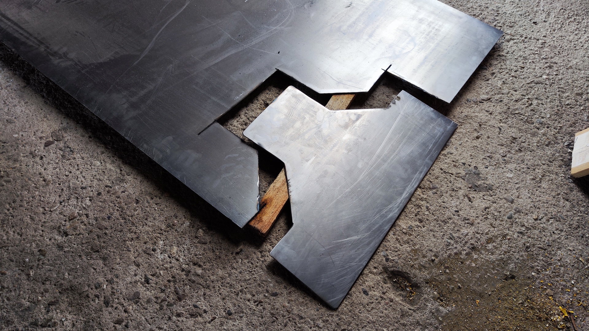
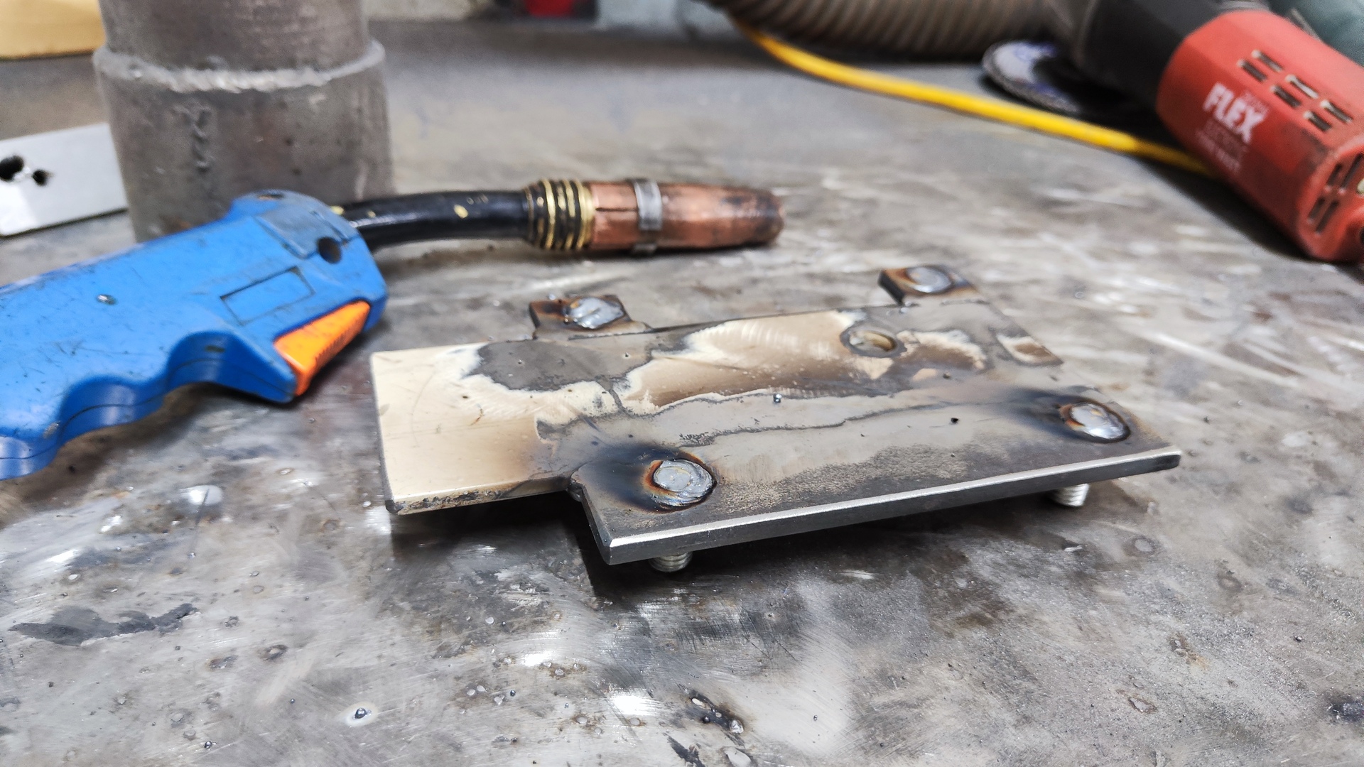
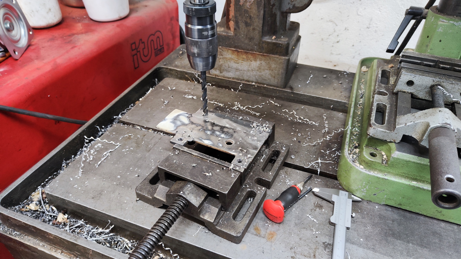
Technical Drawings
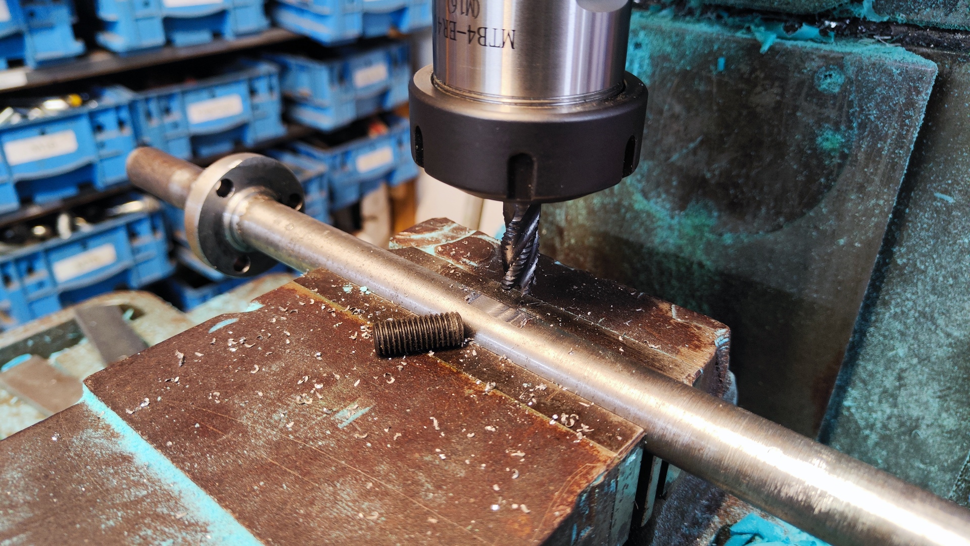
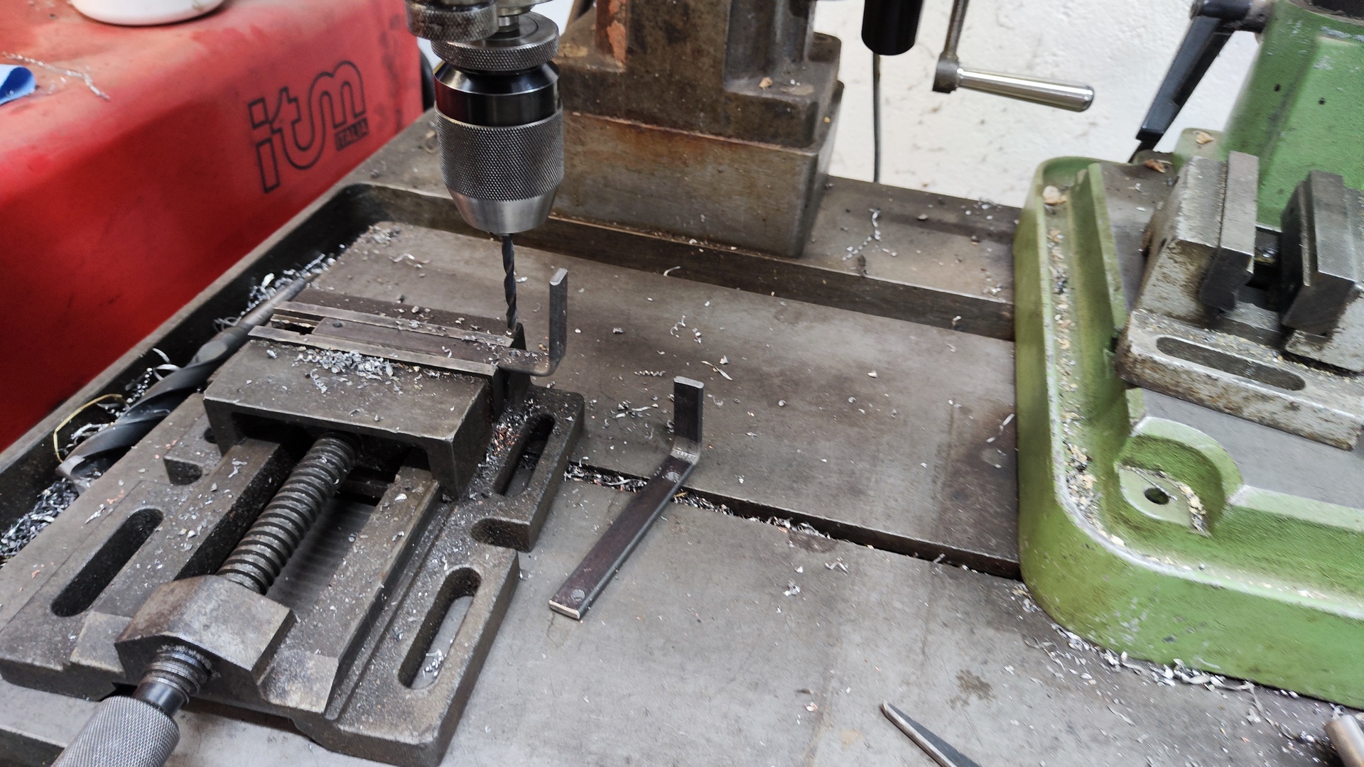
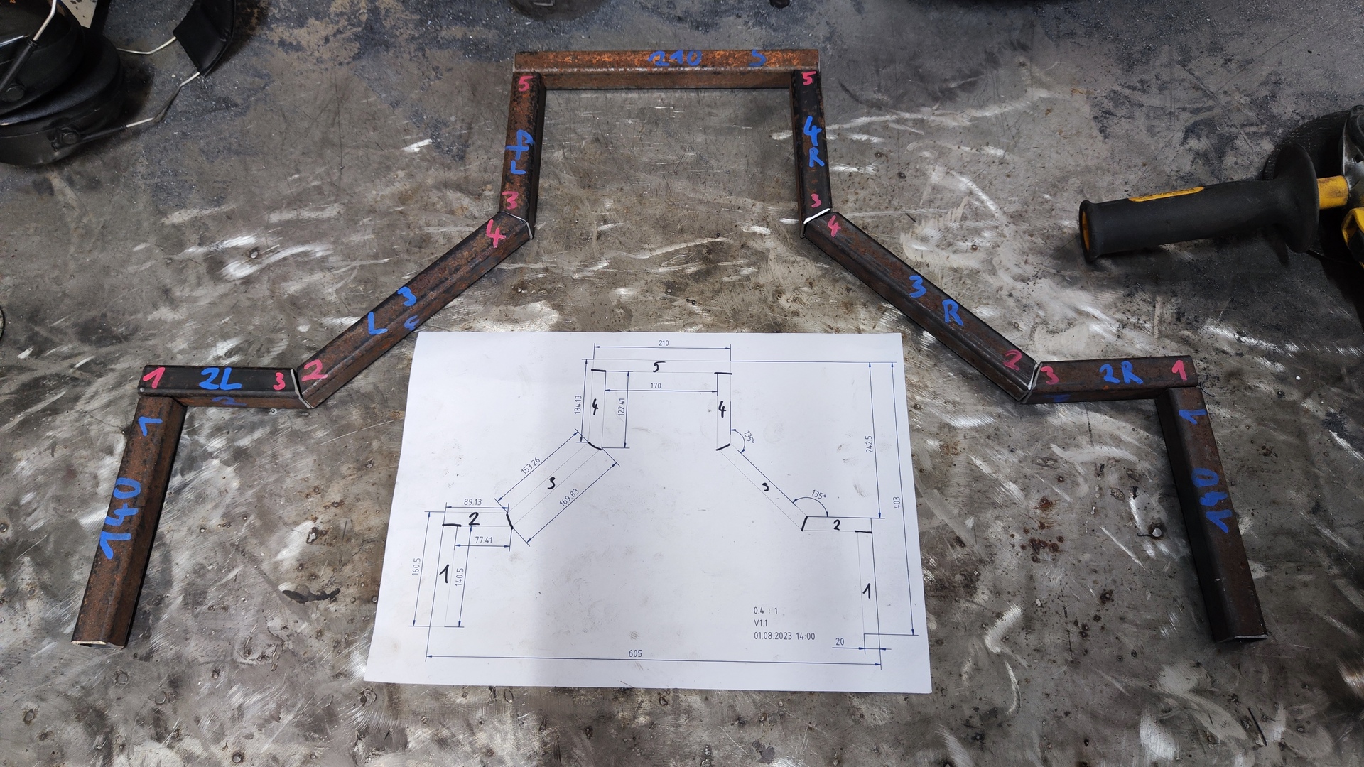
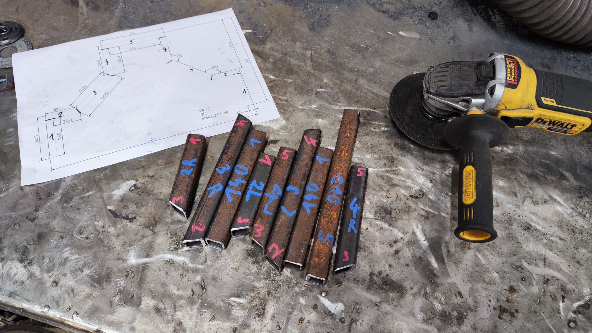
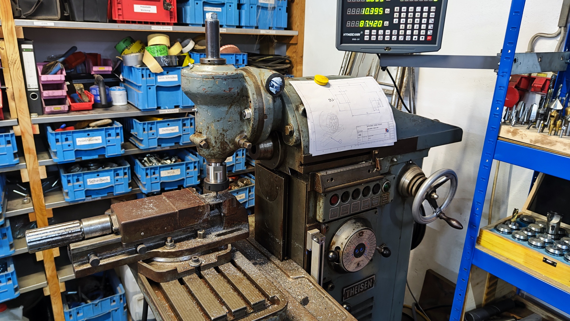
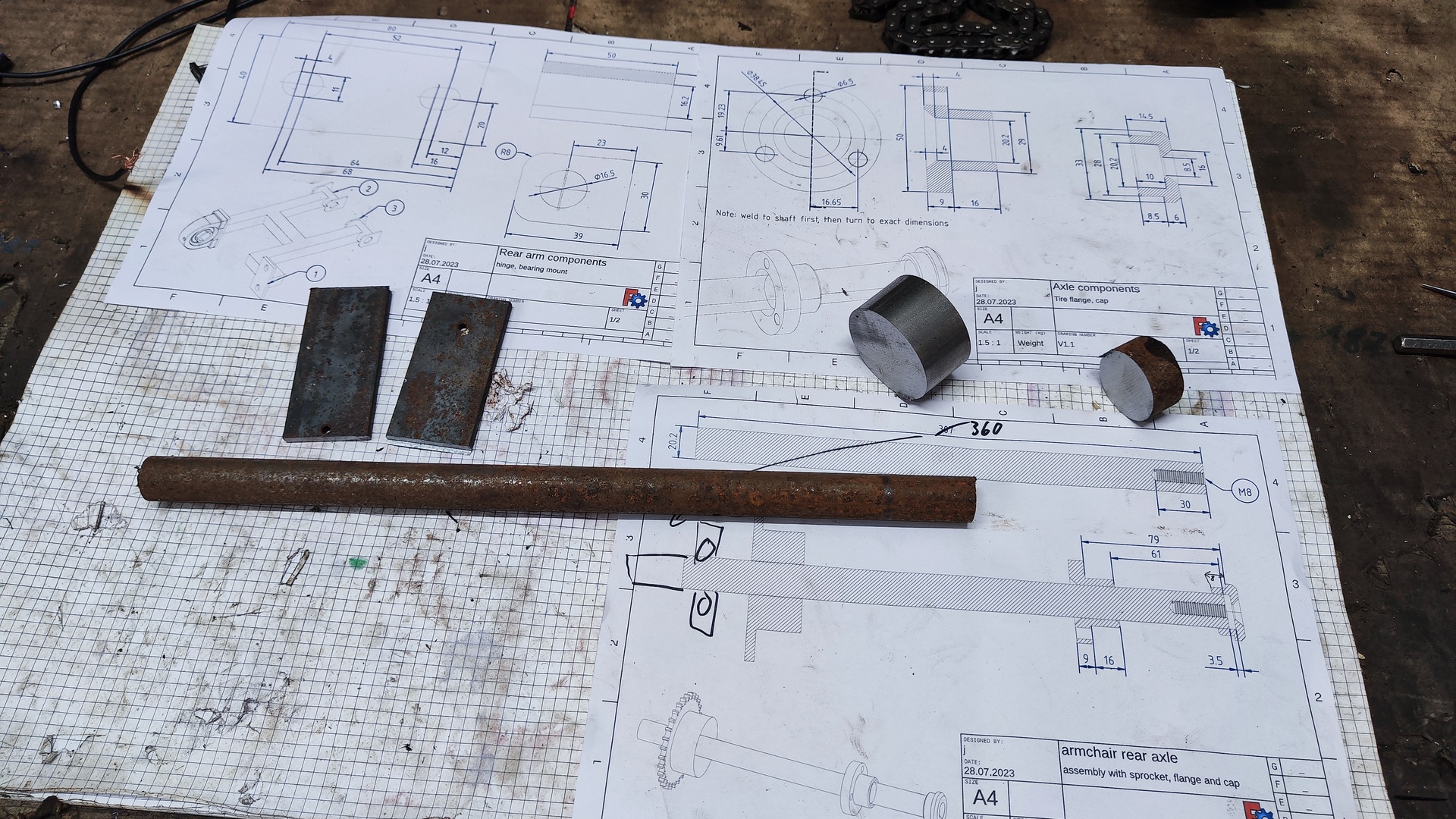
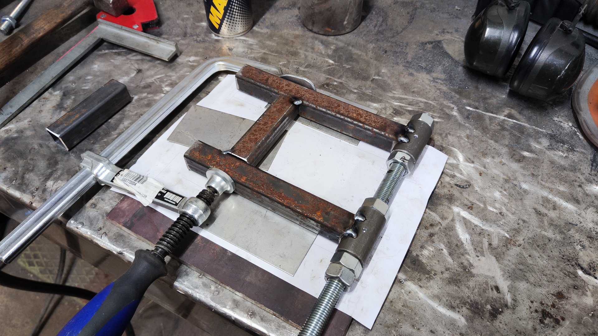
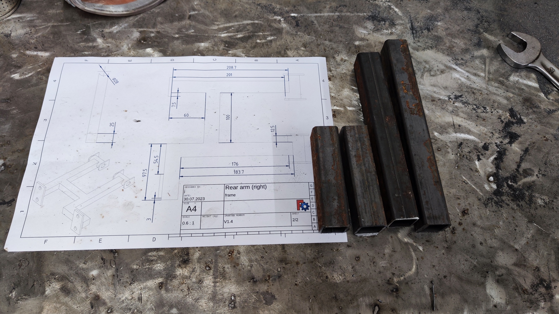
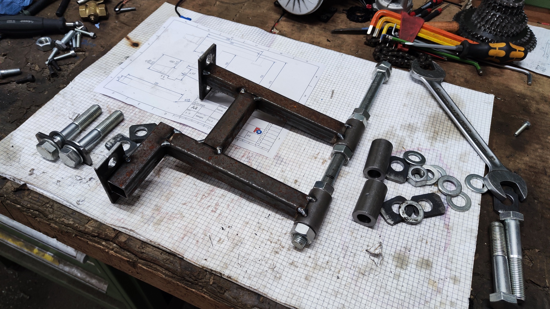
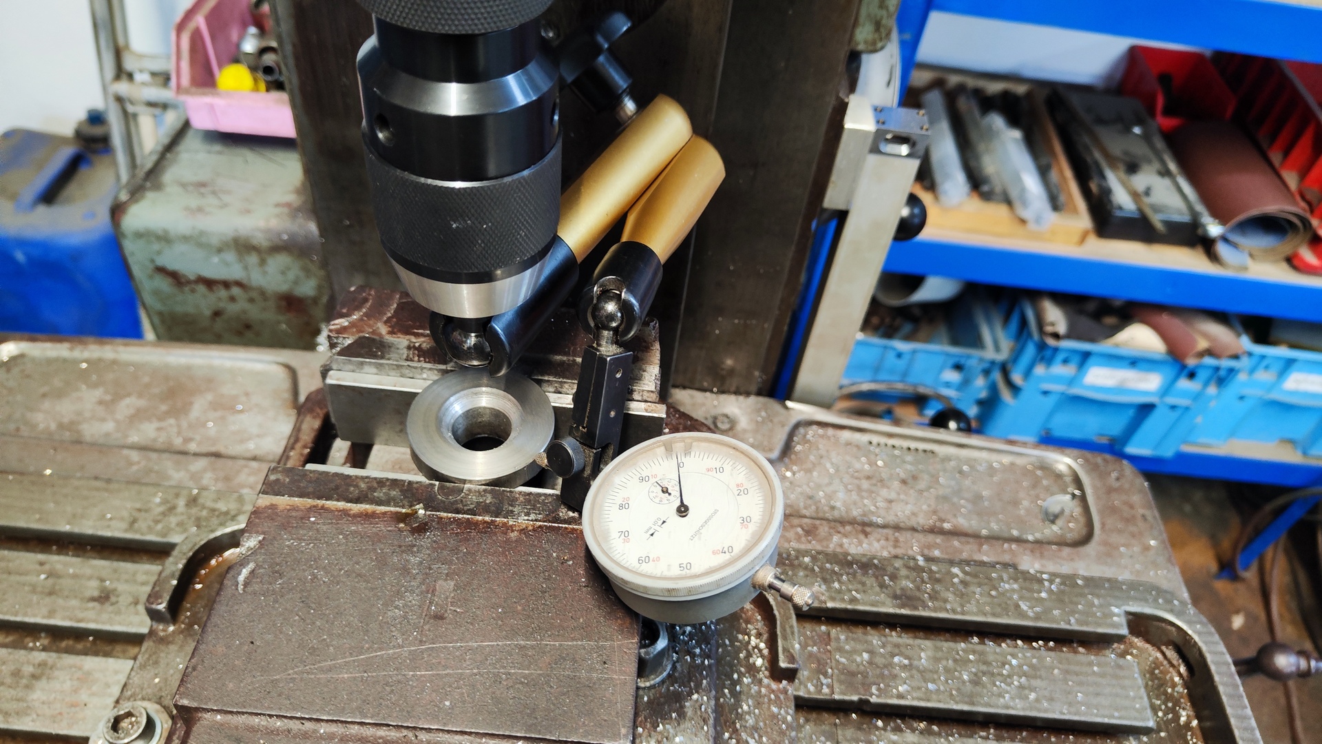
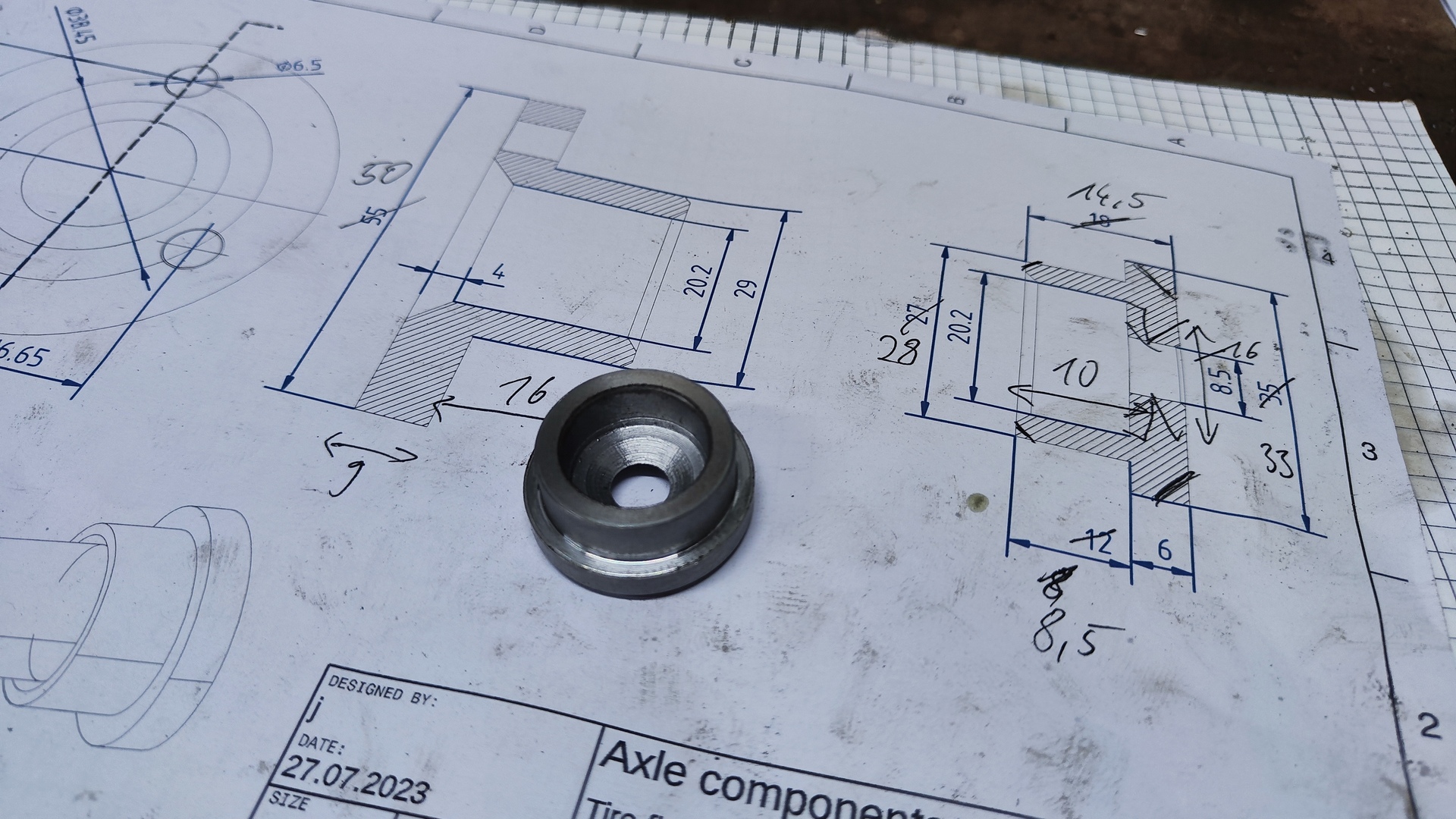
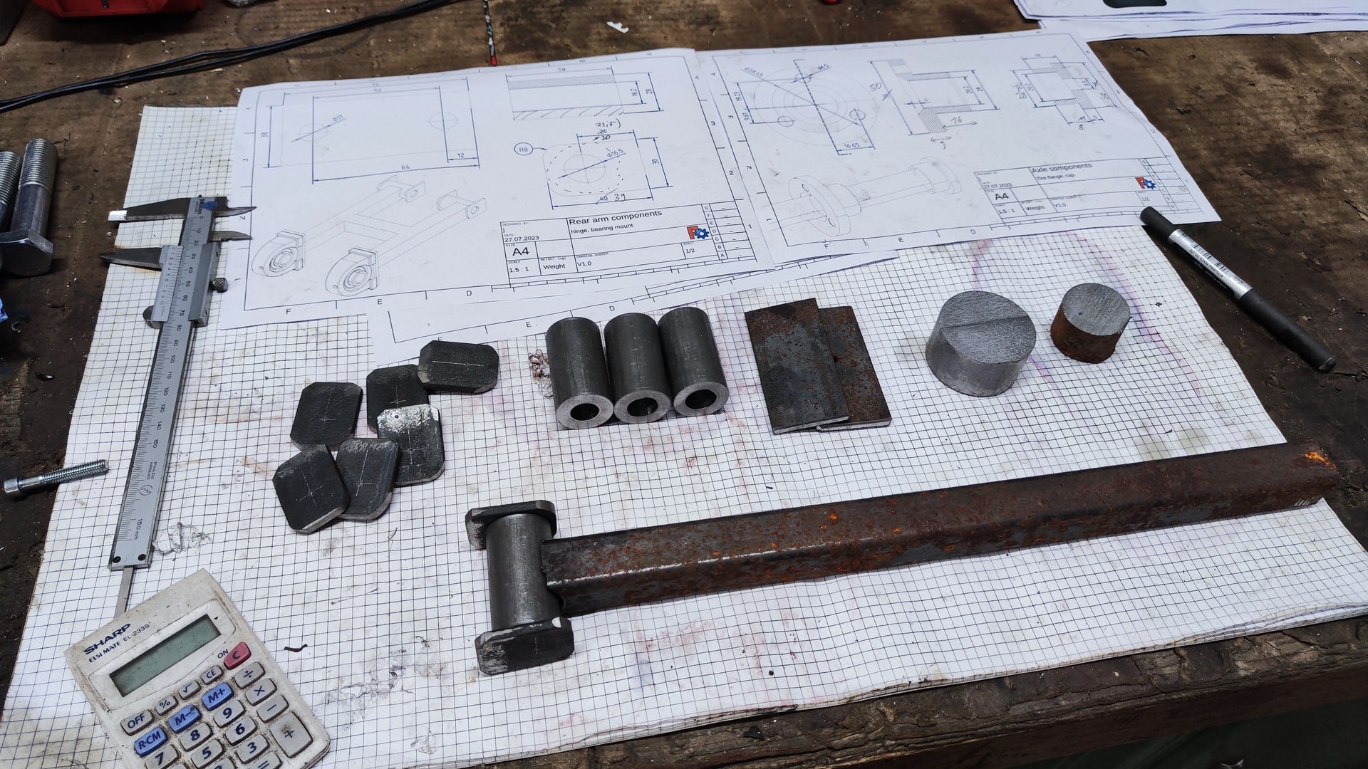
All components were designed in FreeCAD, and manufactured according to the created technical drawings.


You can explore the detailed plans of all metal parts in this document: technical-drawings.pdf
Difficulties
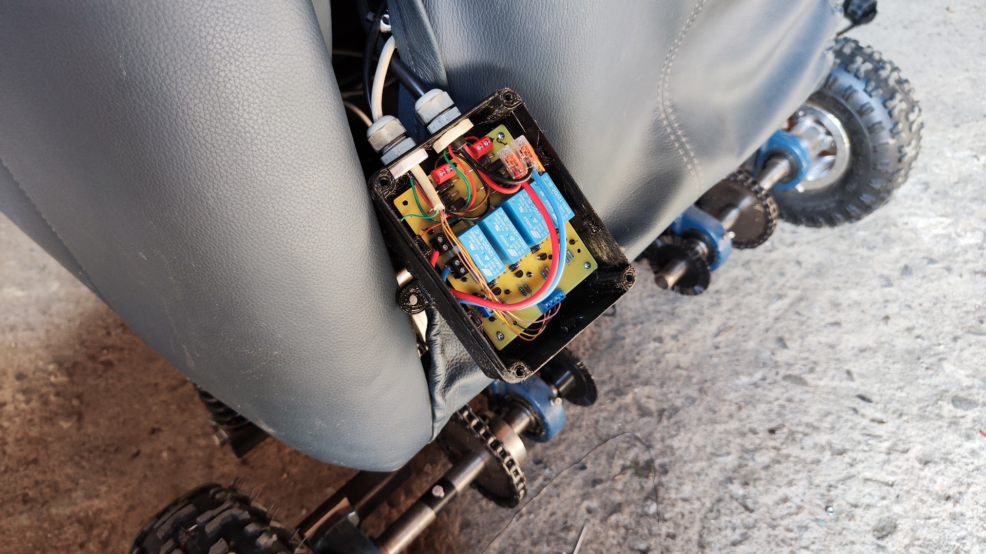
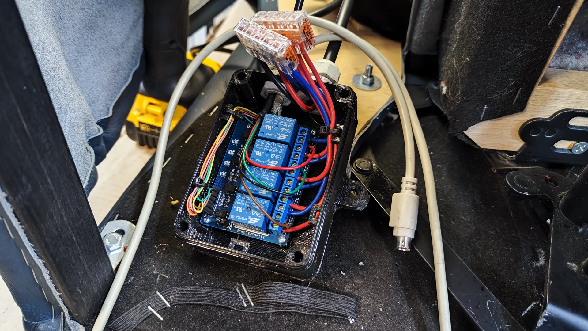
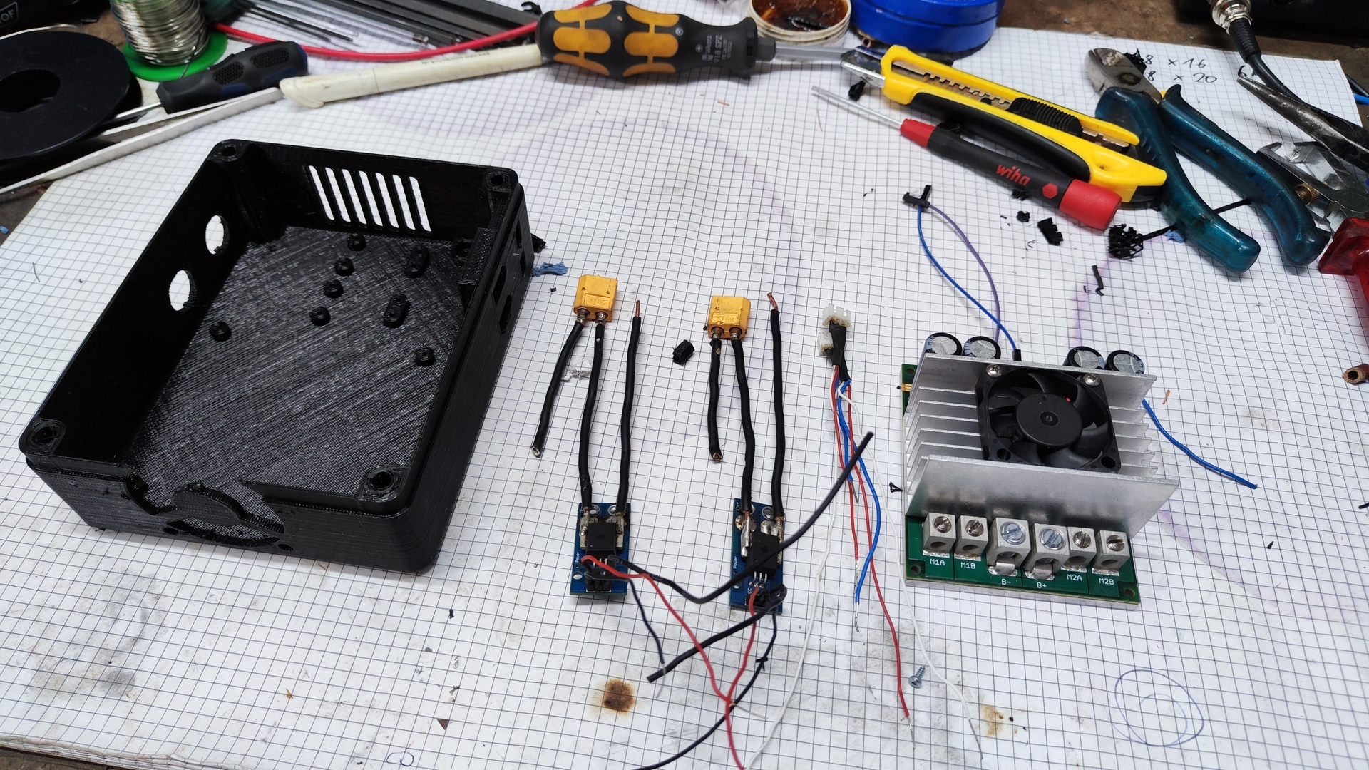
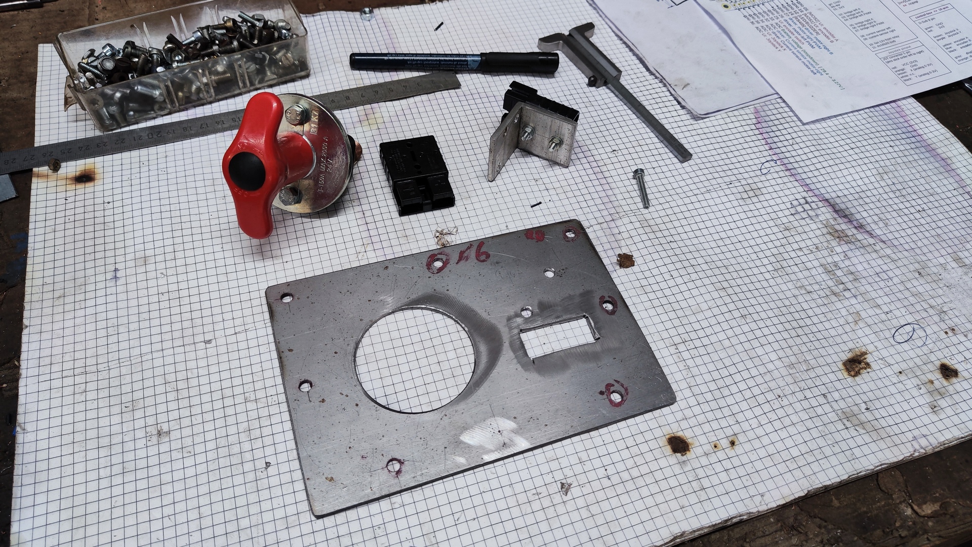
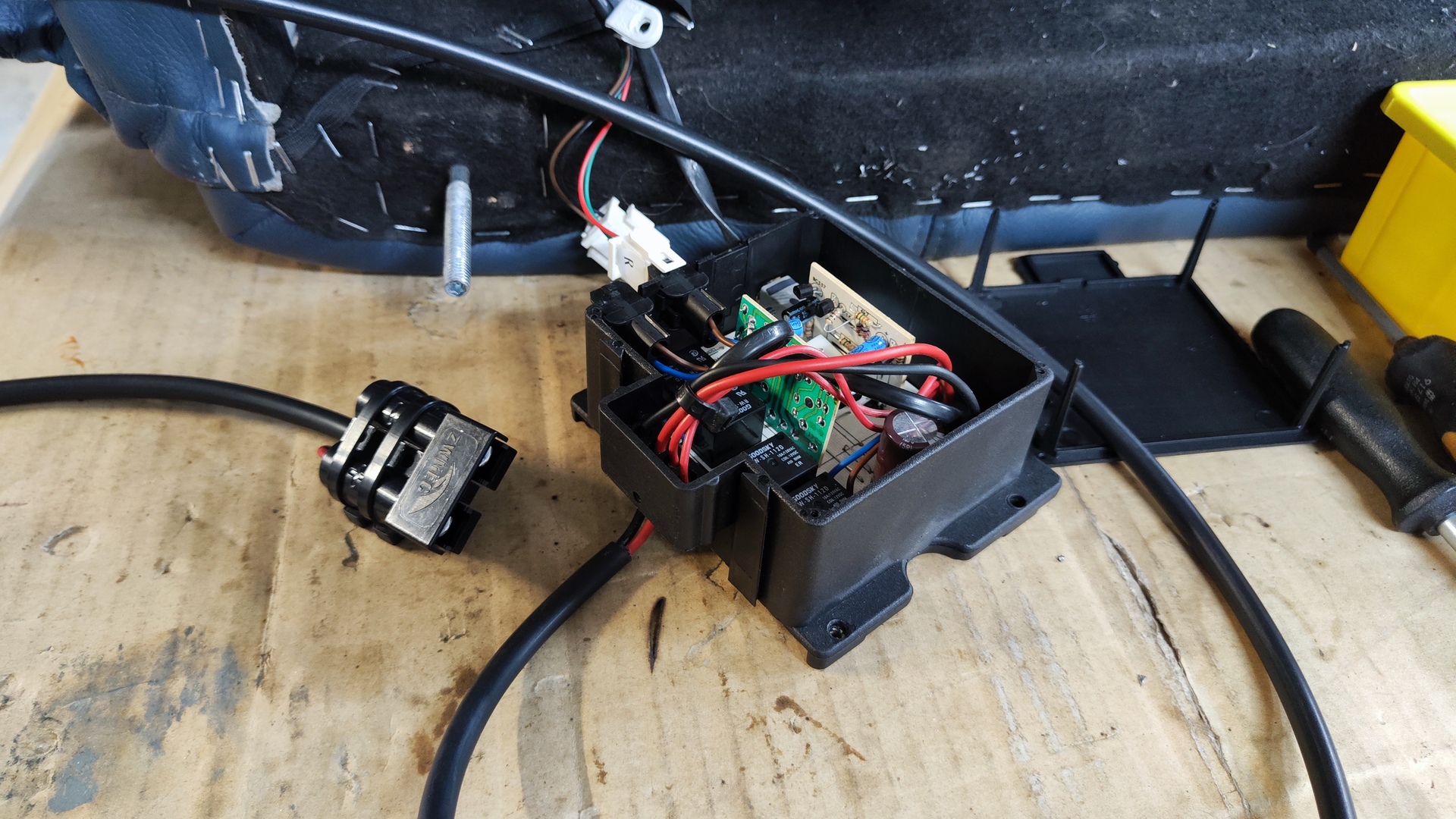
Relays Welding Issues
Problem:
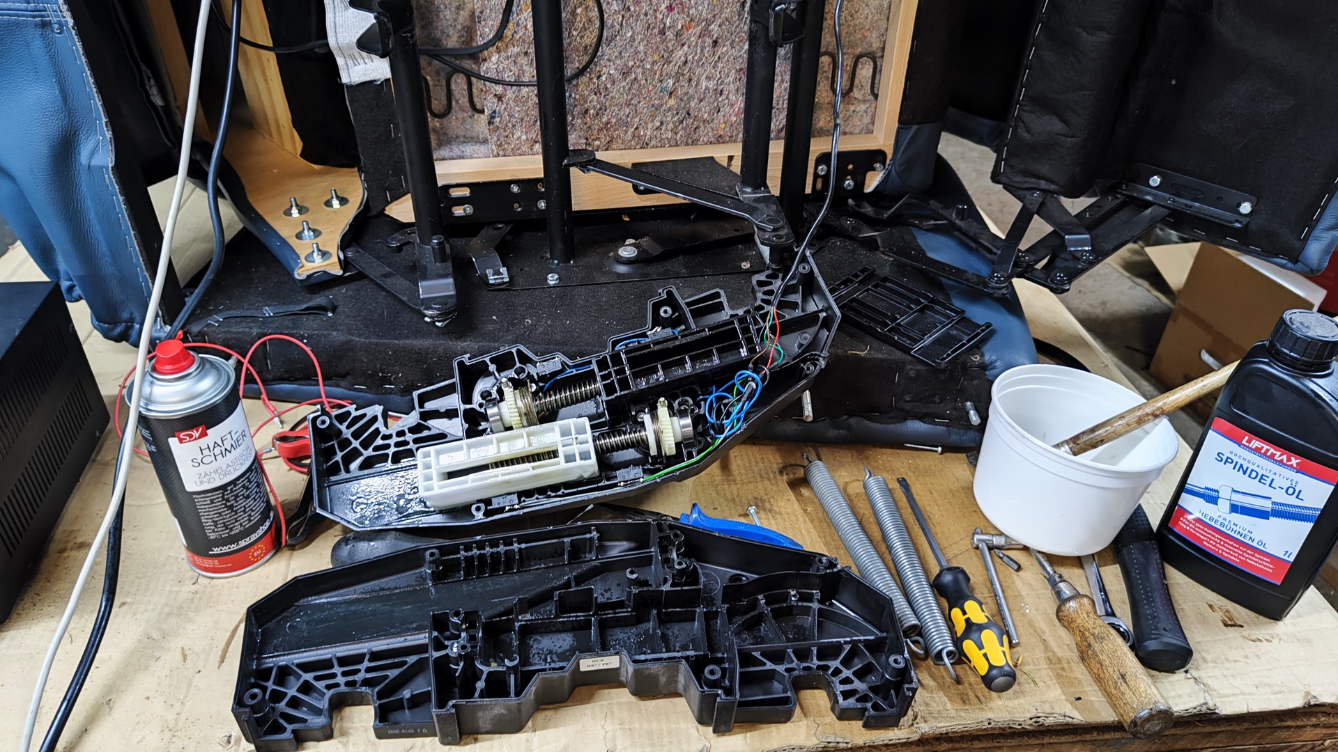
Two 3A 24V DC motors need to be controlled in both directions to adjust the chair rest-positions.
However, even though minimum delays between switching actions were implemented, the relays on the purchased 4x relay board occasionally welded, causing them to get stuck or even short all contacts and blow the fuse.
Solution:
A custom relay board was designed and built using more powerful relays, along with freewheeling diodes to mitigate the EMF-induced sparking during switch-off.
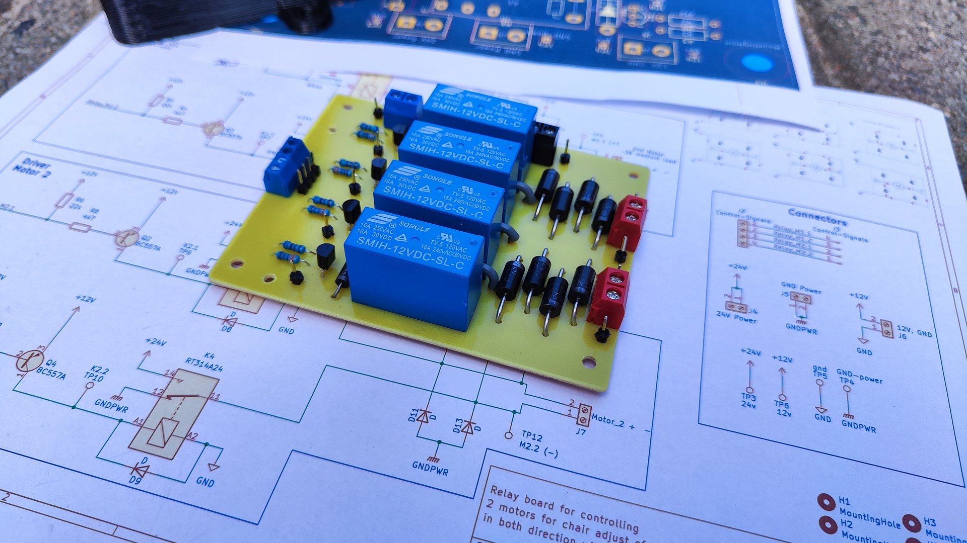
 Schematic of the relay-board
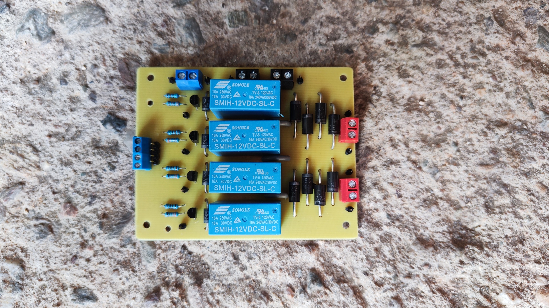
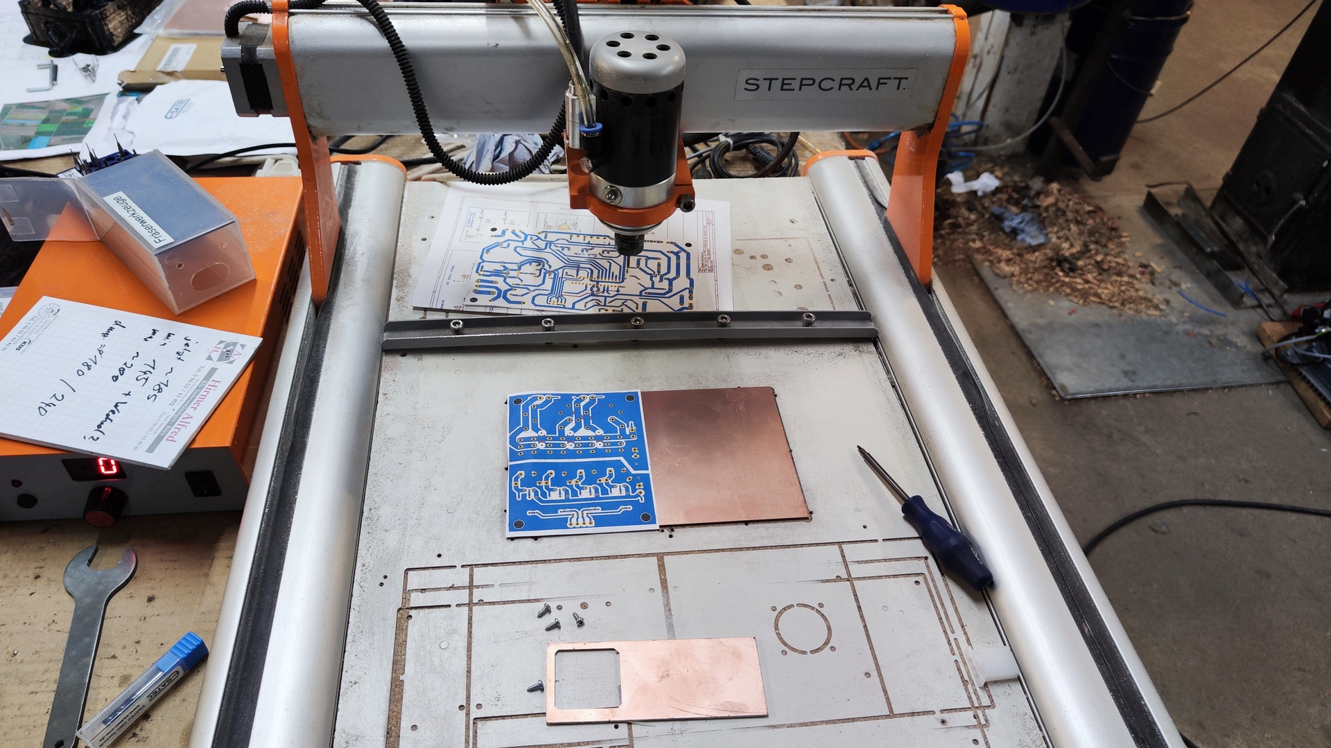
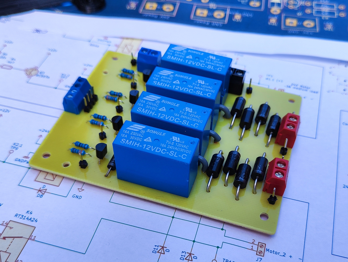 Photo of the finished pcb for controlling the rest-motors
Not enough pins
Problem:
The control interface of the previously used motor drivers already required 5 GPIO pins in total (A, B, PWM). With the introduction of new components like the display, rotary encoder, speed sensors and planned future sensors, there weren’t enough available GPIO pins on the ESP32.
Solution:
Two-board approach: One board controls the motors (driver, current limit, fading, etc.). The other handles the user interface and generates motor commands. Those boards communicate via UART.
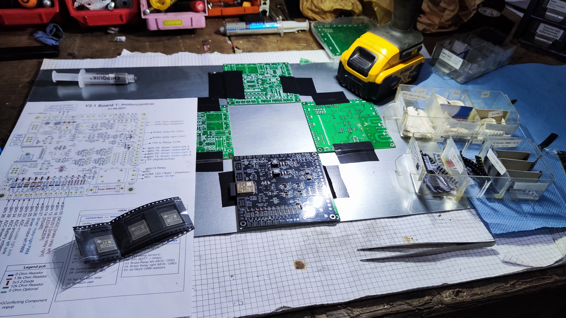
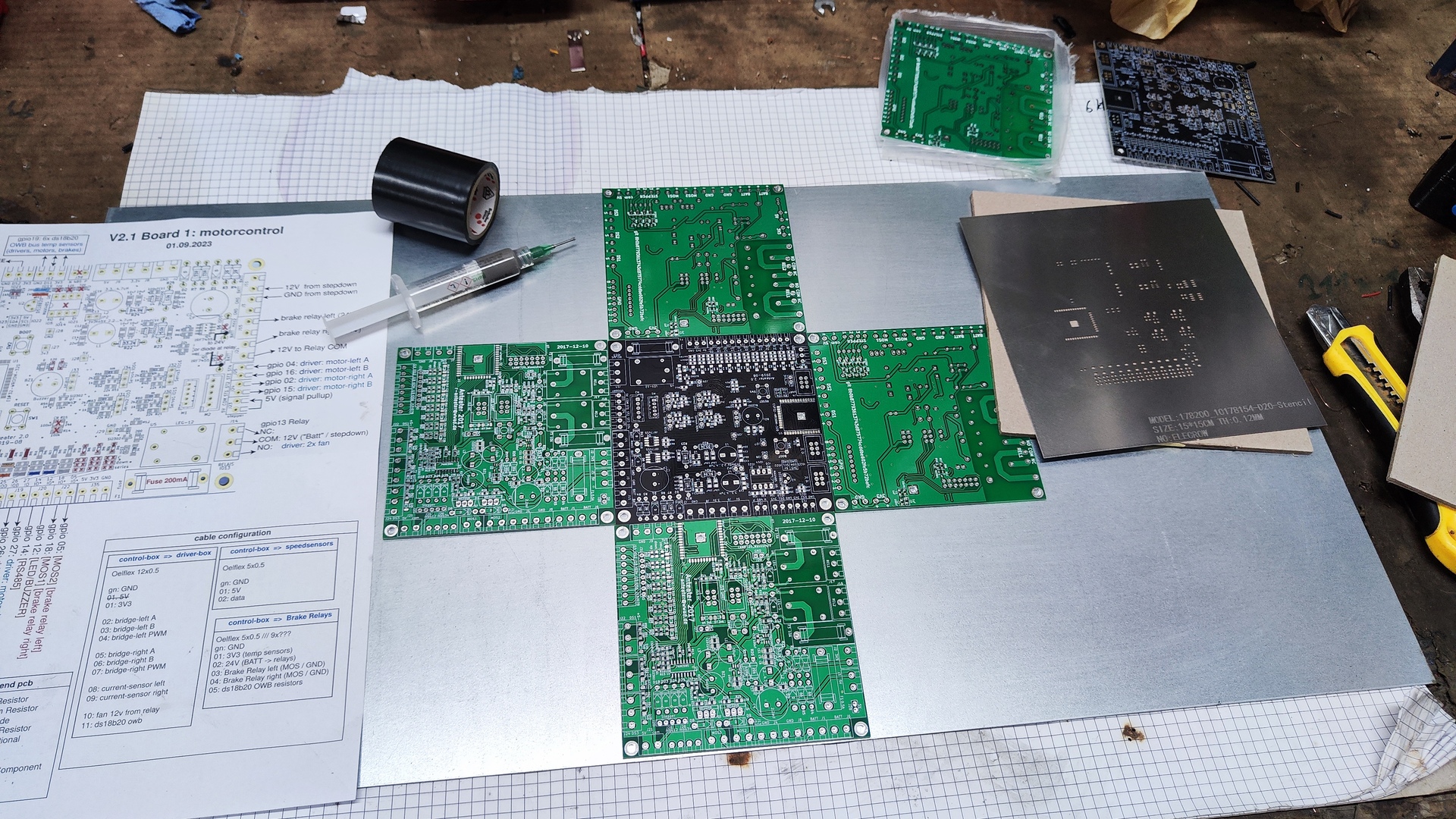
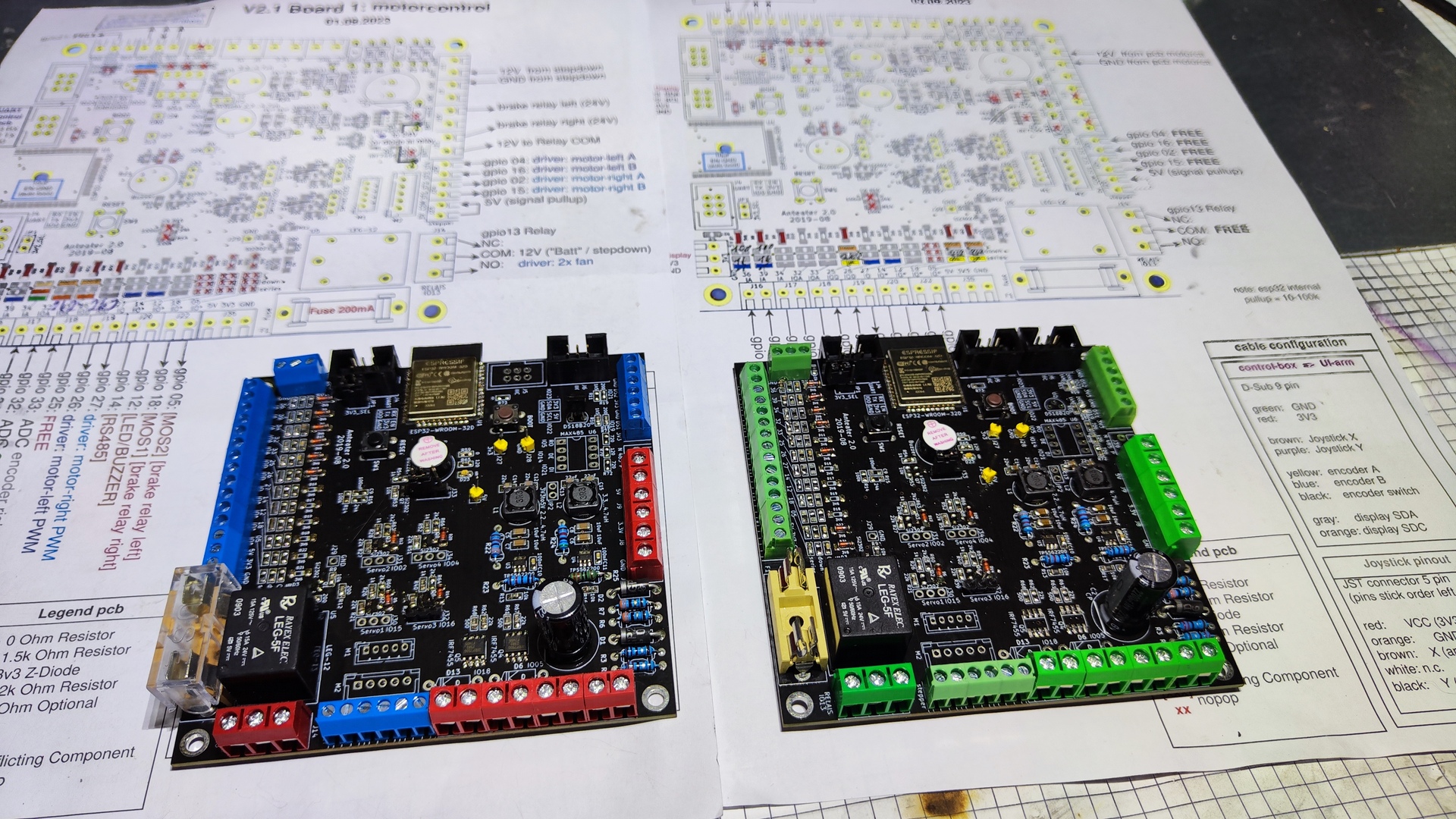 The two boards newly populated according to plan: V2.1 (page 4-6)
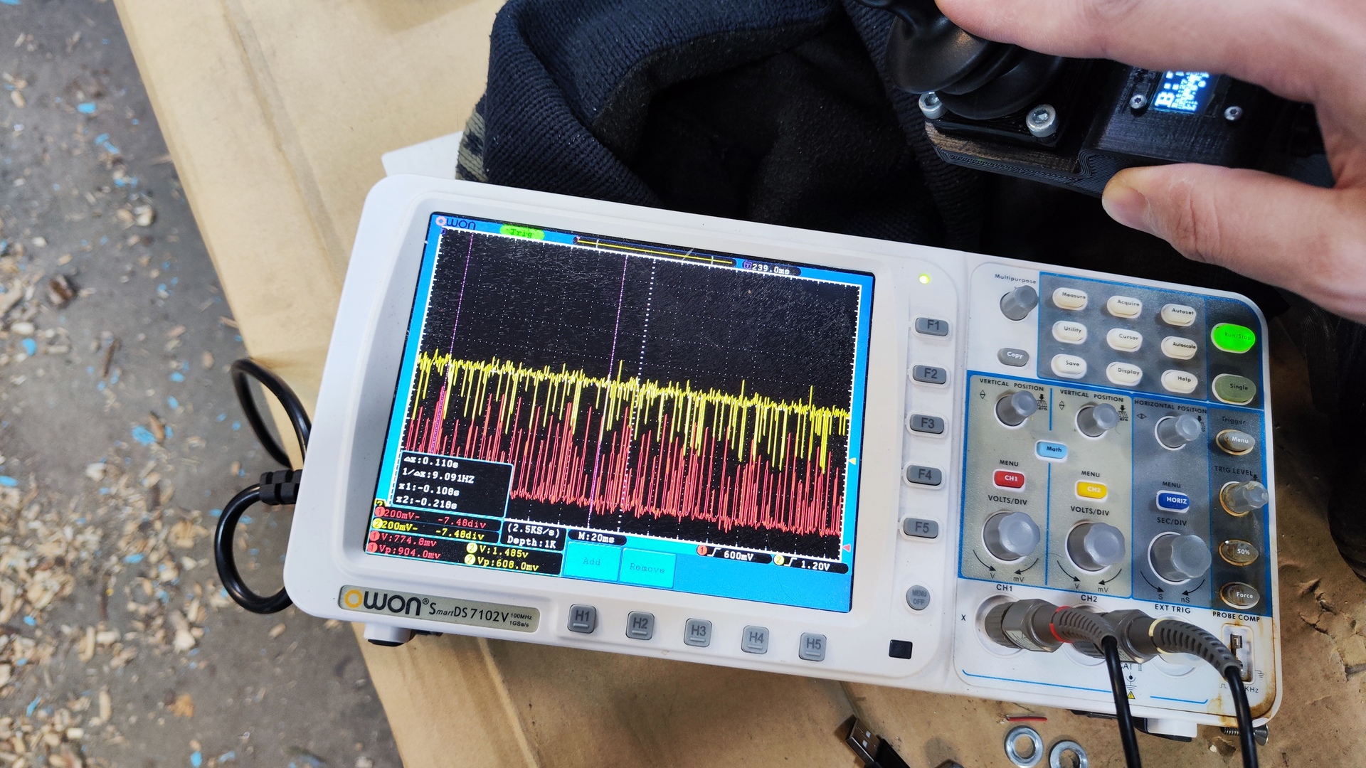
Driver bug
Problem:
The cheap motor drivers caused a dead time for several seconds when reducing duty cycle while the motors were still generating voltage. This was due to an error in hardware design of the driver. The control voltage being the difference between input and output voltage, without a separate regulator.
Debugging Driver: Does not respond to signal, when generator voltage exceeds 14V at low duty cycle.
Solution:
As workaround two relays and power resistors were added to briefly toggle the motors on and off. This helped in the recovery of the control voltage and also could be used to dissipate power during braking, protecting the motor drivers.
Schematic: V2.1 Driver box overview (page 7)
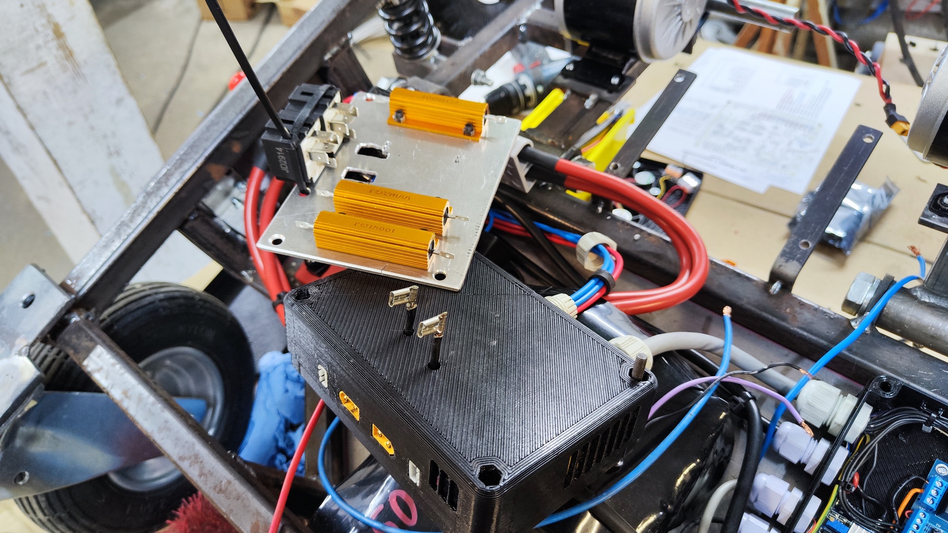
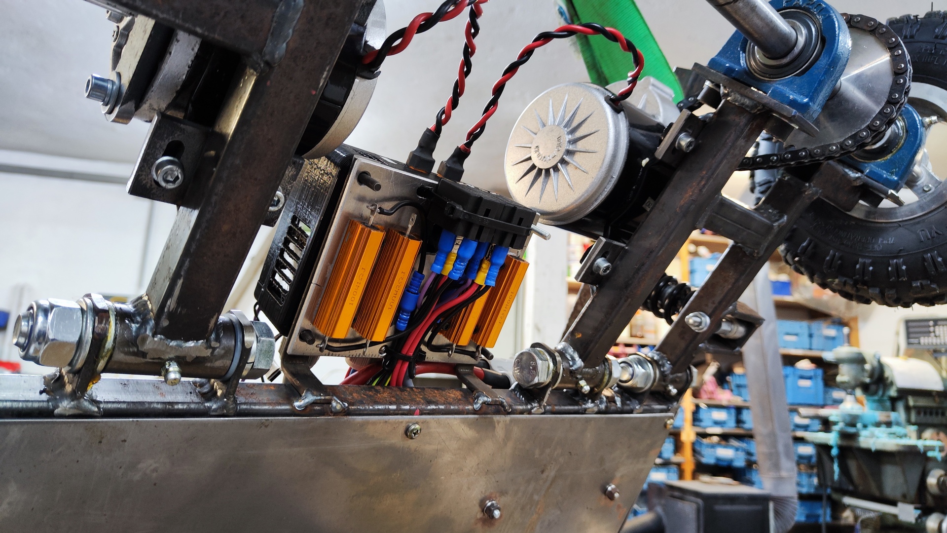
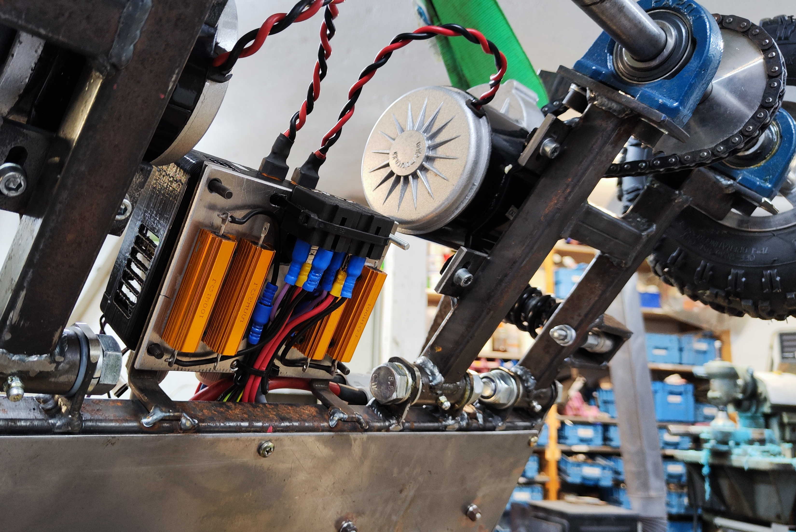 Aluminium plate with brake resistors and Relays added below the motor driver box
Unreliable Drivers
Problem:
Initially, the inexpensive motor drivers from the previous armchair design were used: HC240A-PWM rated for 8-30 V and 30 A.
However, even after the previously mentioned optimizations these drivers continued to burn out.
This was primarily due to a slightly higher battery voltage and increased tire grip, resulting in higher current demand that slightly exceeded the specified limits.
Solution:
A switch to a more powerful dual-channel motor driver (2 x 60 A) was made. It is controlled via a single-pin serial interface (RS232). This switch made the second board and braking resistors obsolete.
Overview of the current setup: V2.2 (page 1-3)
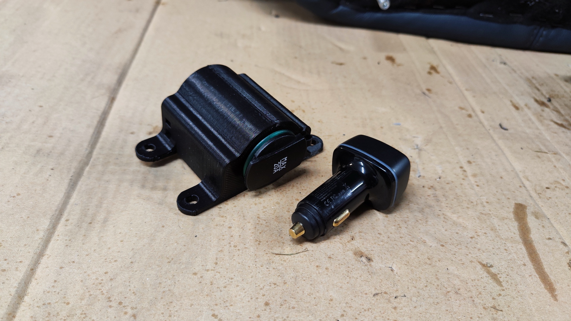
 Previously used cheap motor drivers
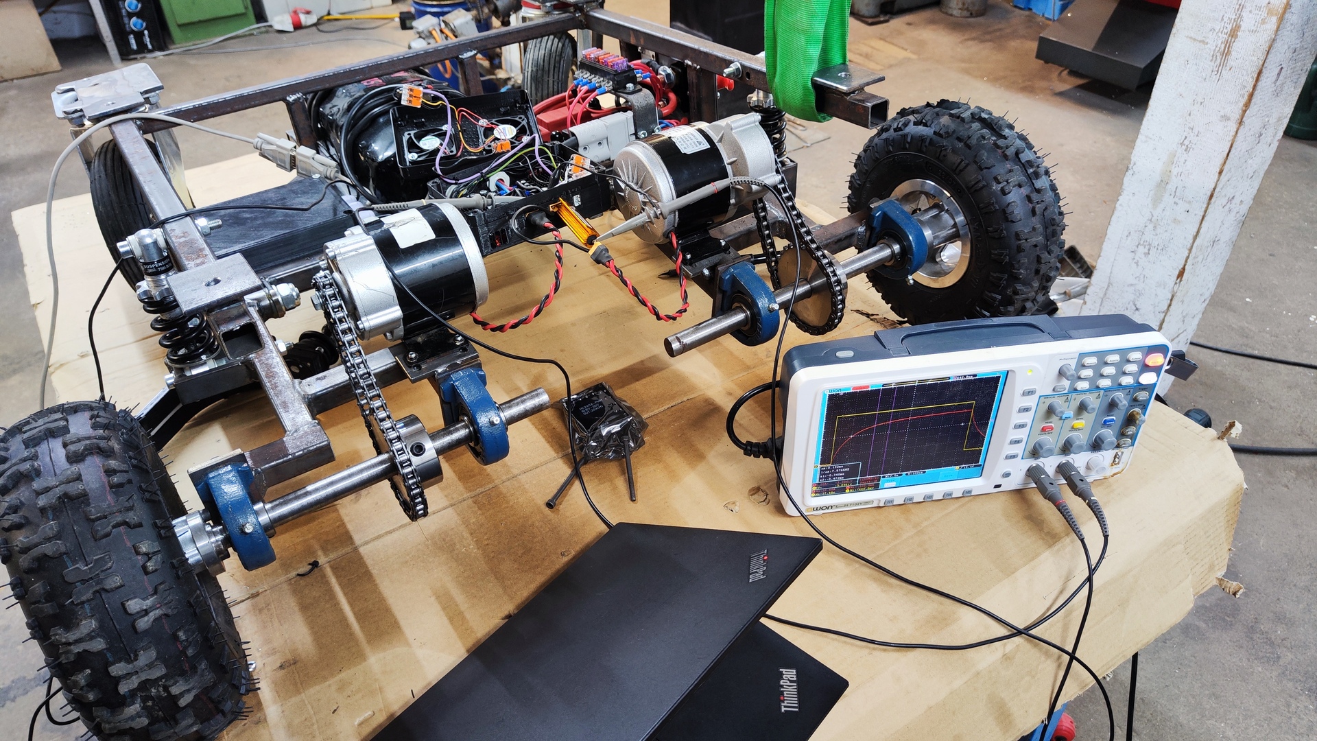
Videos
Tests
Suspension test
Test drive frame
Rotate
Drive
Fails
Crash into fireplace
Crash into bench
Gallery