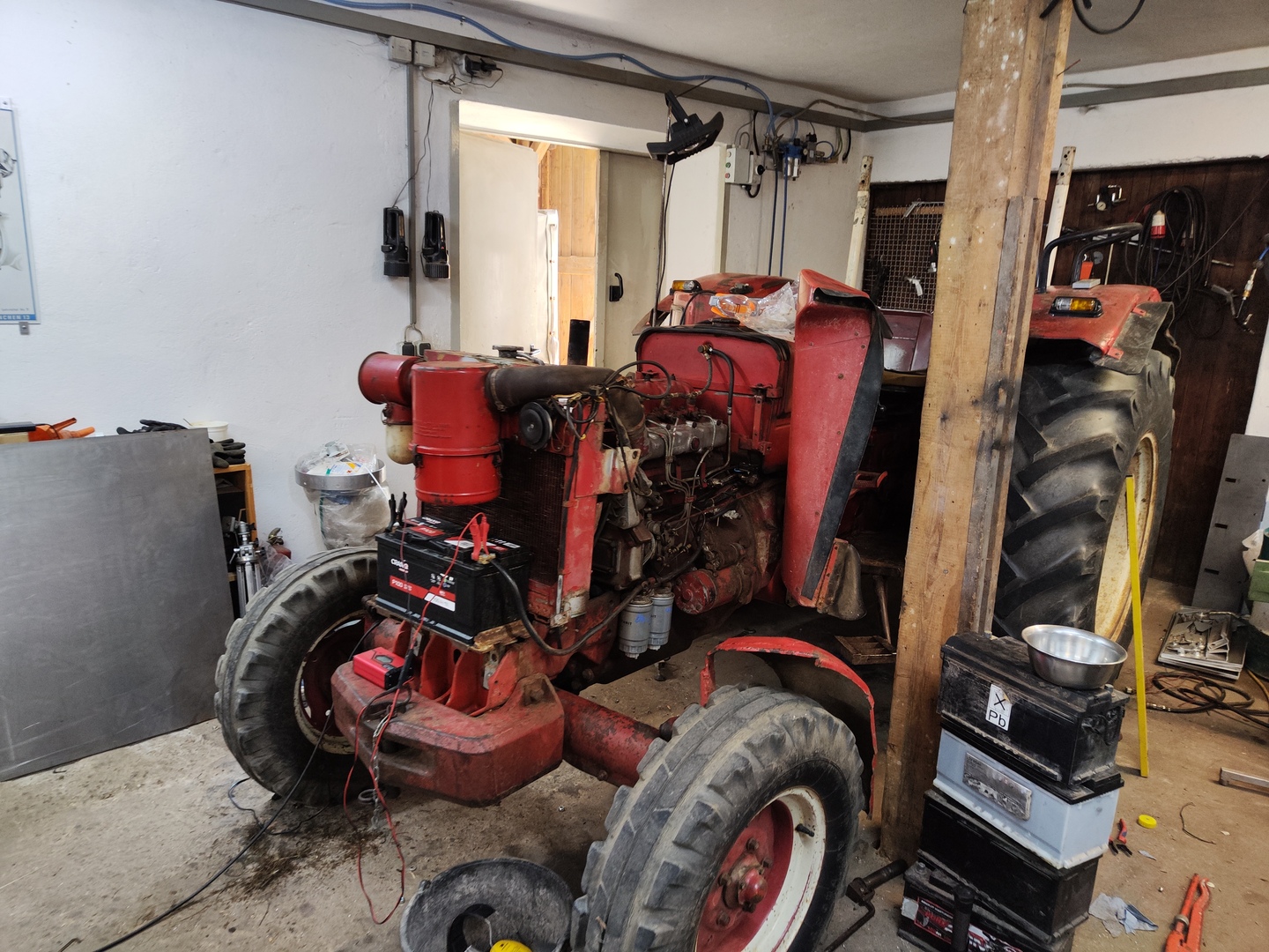
Custom pcb for controlling the electric components of a tractor with a microcontroller. During the restoration of an IHC-tractor a custom pcb was developed and built to replace the broken relay based control.
Goal
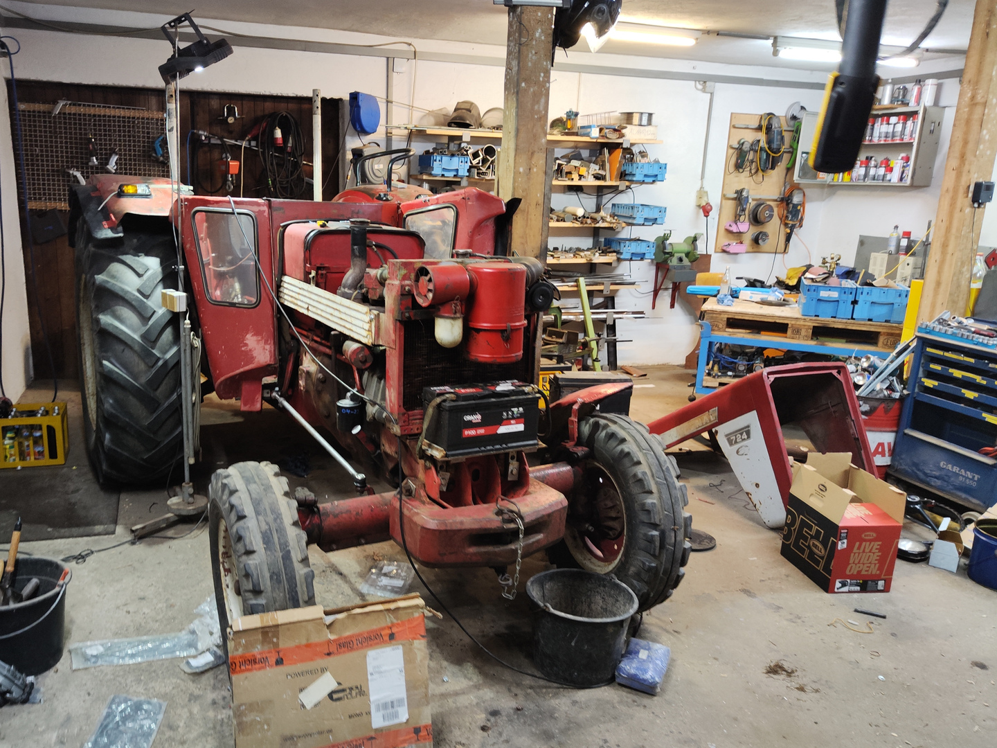
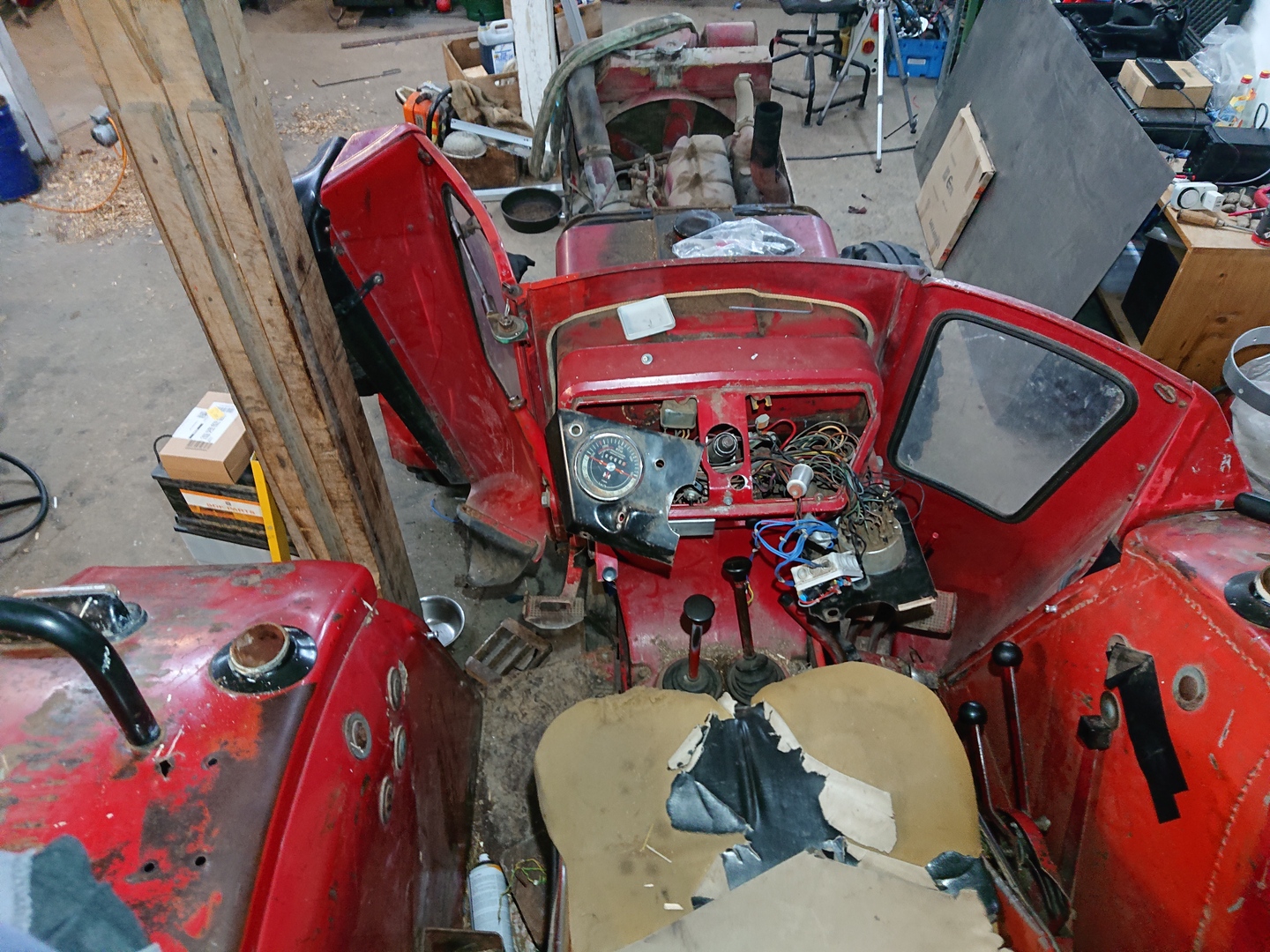
The electric system of this tractor has quite some complex logic which was originally implemented using several relays. Because the original setup was significantly damaged over 57 years of extensive use, I decided to rebuild the control by developing a custom circuit board with a microcontroller as core component for easy extendability.
Reasons for this project
- Saving several separate original components, thus saving money and reducing the chance of faults:
- Flasher unit for blinker
- Flasher unit for warning lights
- Wiper control unit
- Special relay for high beam
- Special indicator switch
- 3x relay for brake light logic
- Much less wires, since all the logic is done by one pcb
- Flexible logic
- New features:
- Low voltage alarm
- Acoustic blinker signal
- Custom horn signals/presets
- Option for more features by just upgrading the firmware
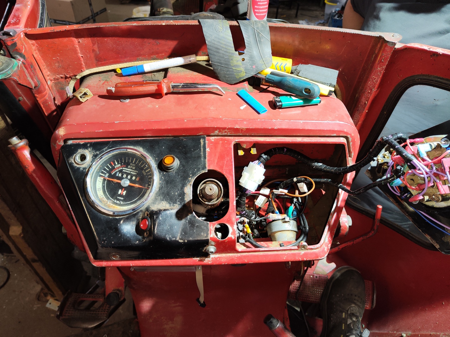
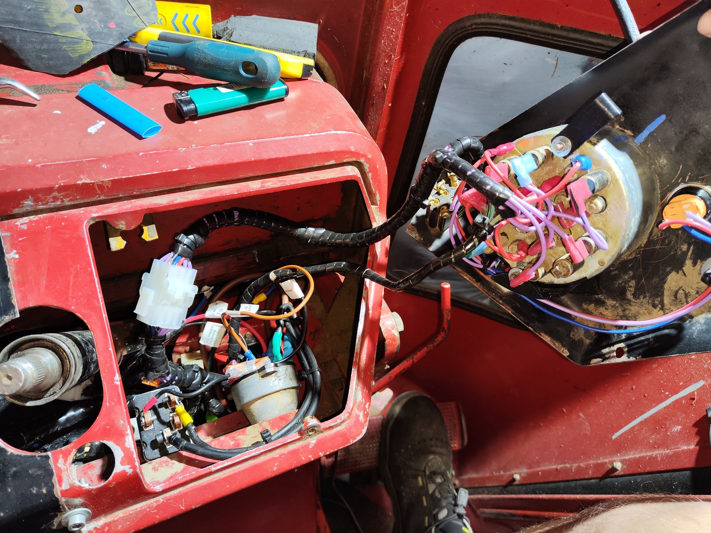
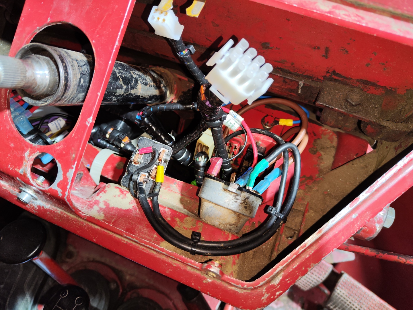
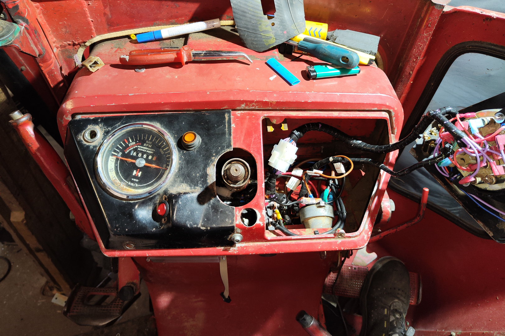
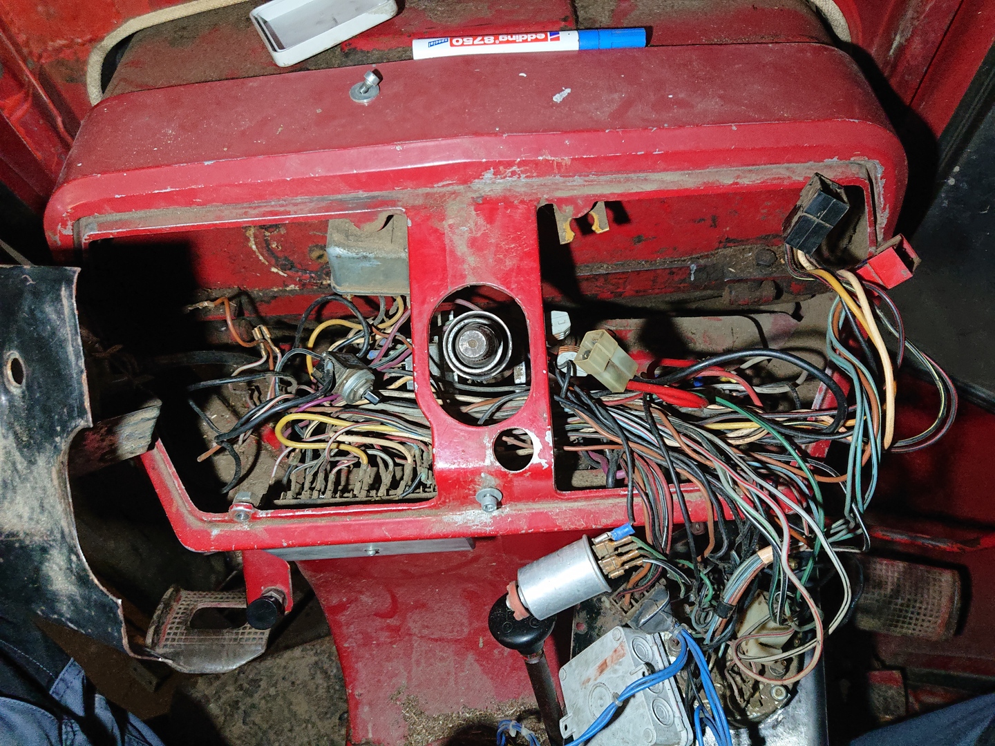 Original wiring
Course of action
Planning
Requirements
- Stable and regulated 5V supply
- Buzzer for acoustic signals
- Connector for programming
- Protected Inputs against electrical interference
-
Inputs:
- 6x digital input (switch to GND)
- 3x digital input (switch to 12V)
- Analog input to measure the input voltage
-
Outputs:
- 2x 17A Mosfet output (GND)
- 8x 16A Relay output (12V)
Schematic
After analysing the existing system and planning the required features a schematic was developed:
 Finished Schematic
Components
- Atmega8 microcontroller
- 8-Channel mosfet array (ULN2803APG)
- 8x 12V 16A Relay
- 2x mosfet (IRFZ24N)
- Wago pcb terminals
- PCB size: 100x160 mm
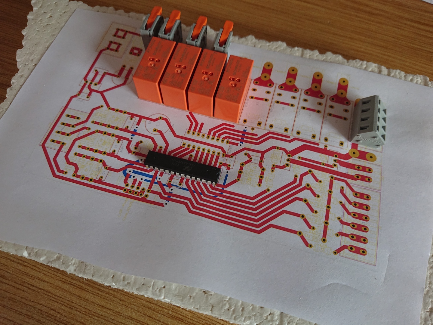
Layout
According to the created Schematic the PCB-layout was designed for a single sided PCB, using as few bridges as possible.
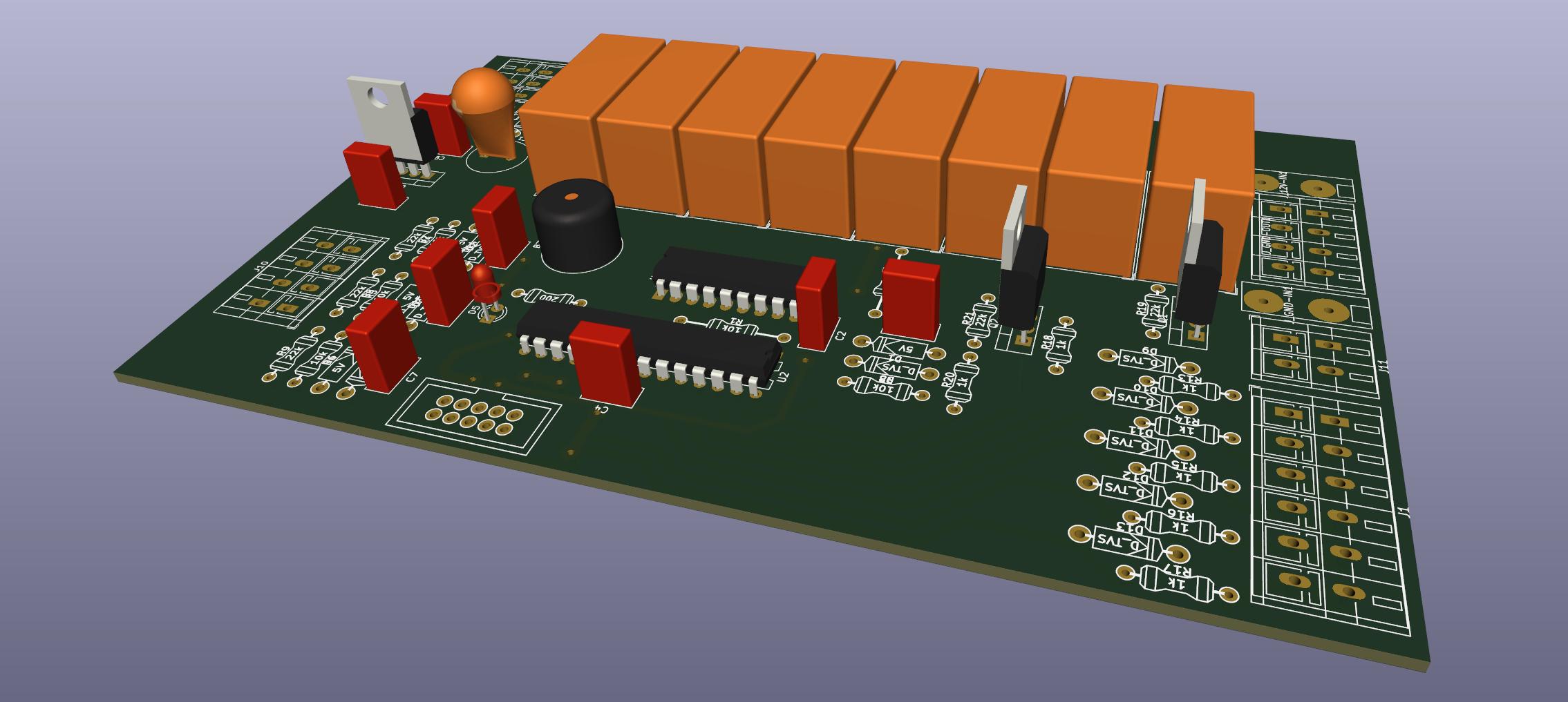 3D model of the PCB
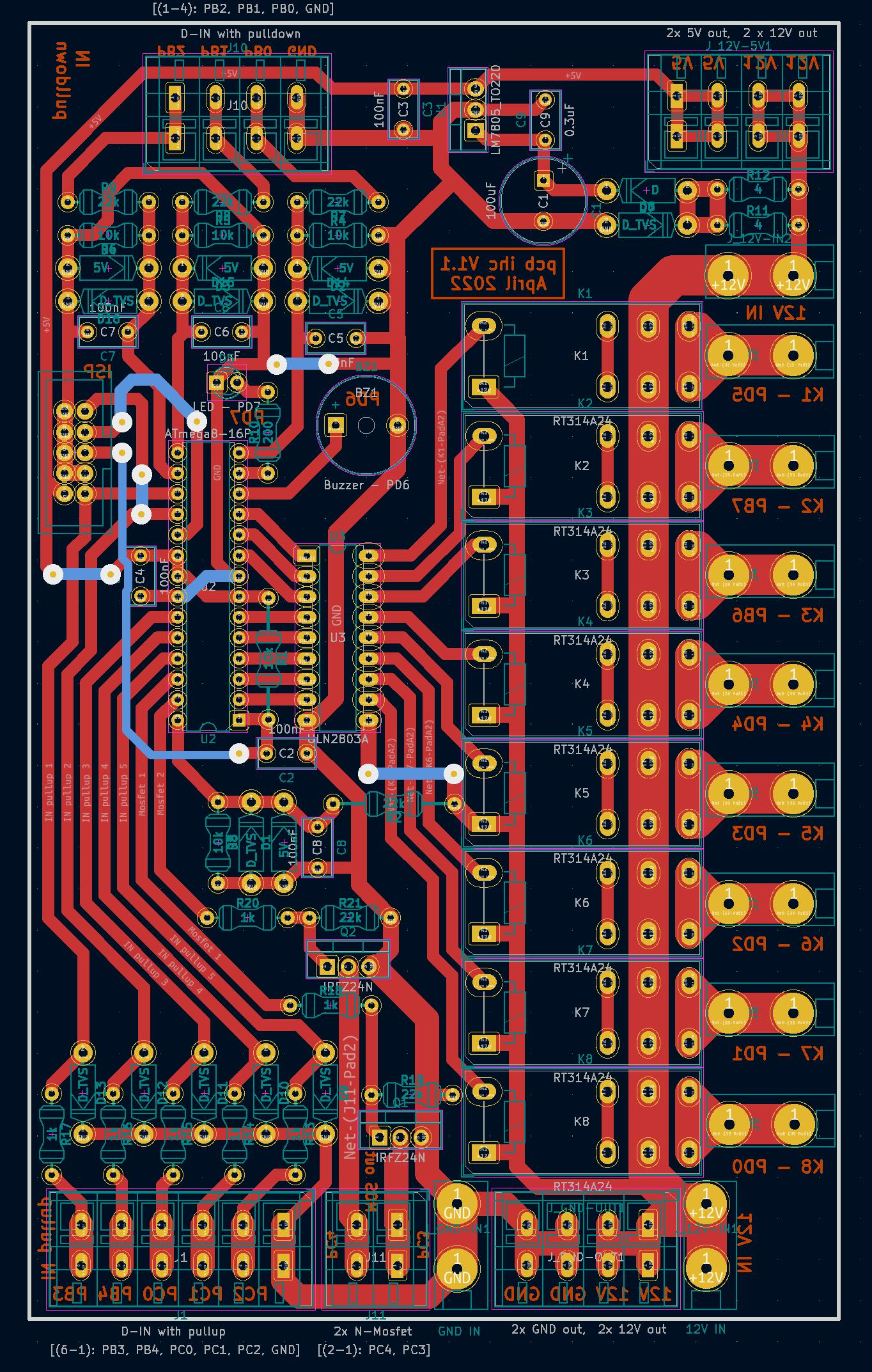 Finished PCB layout
The Git repository for the designed board is available on GitHub.
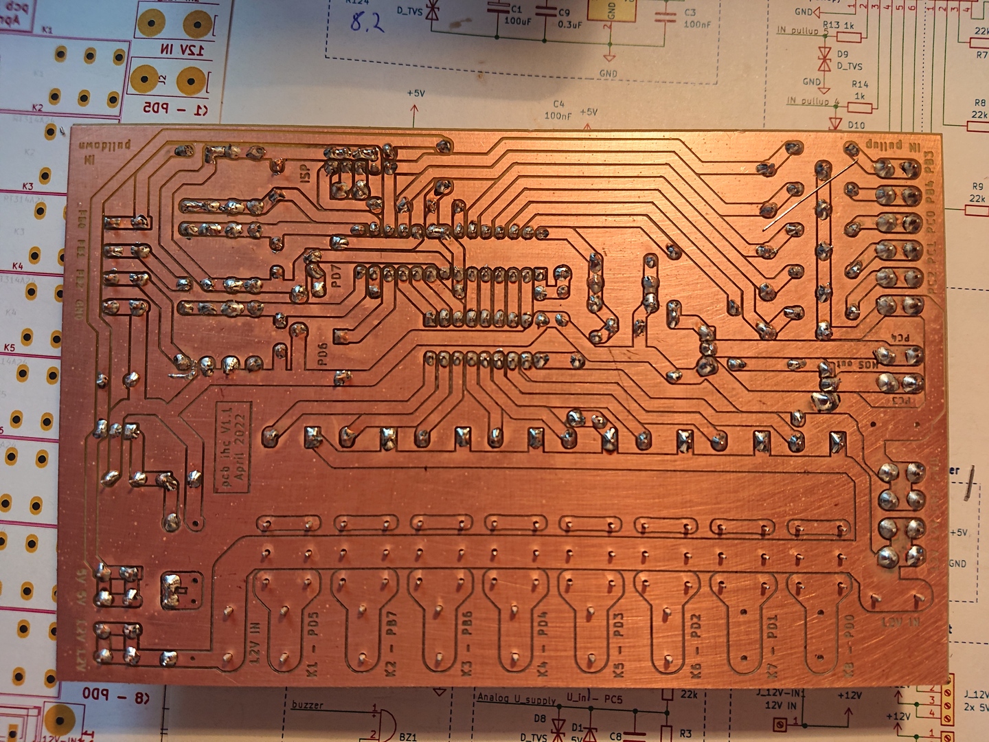
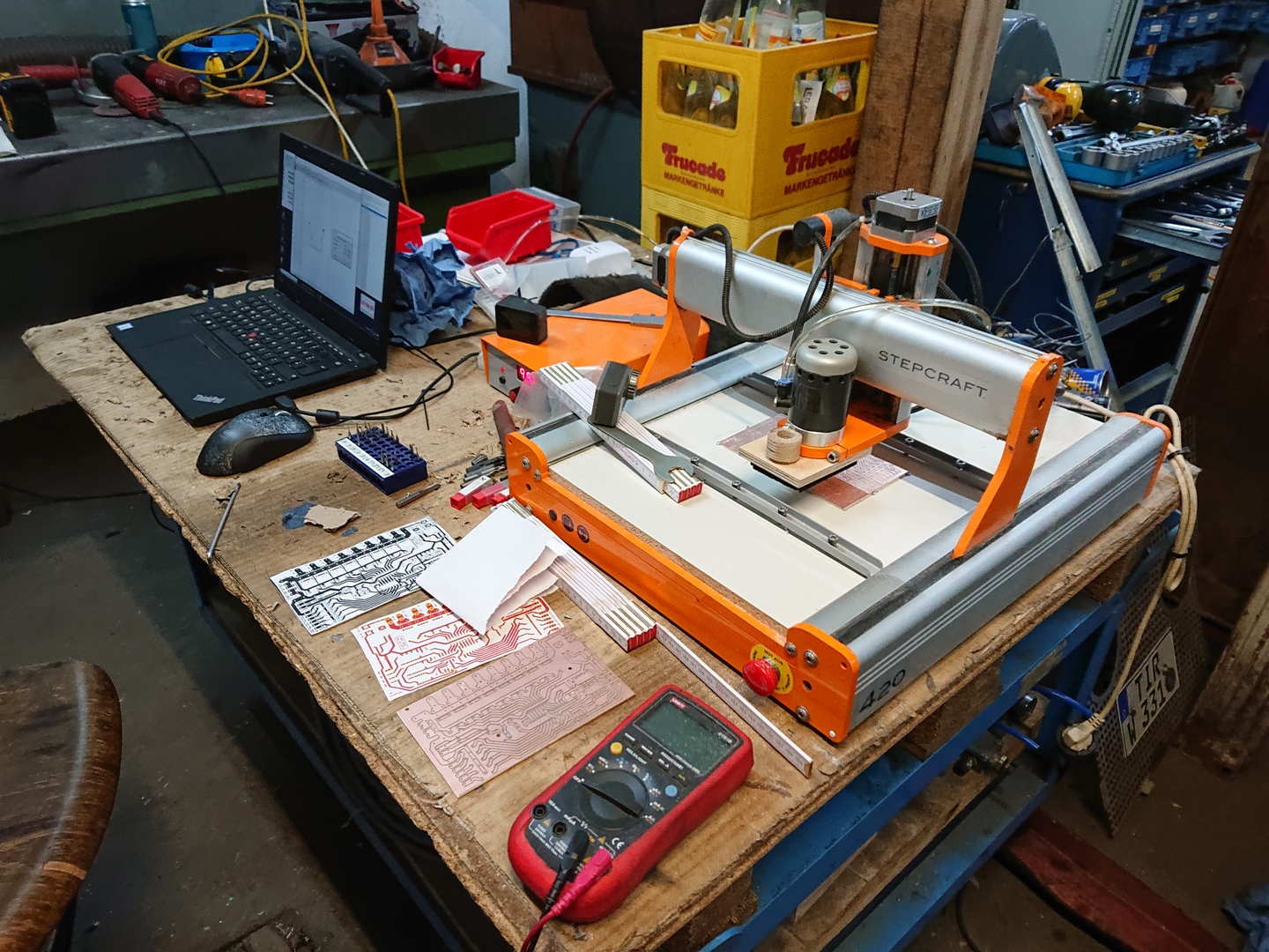
Production
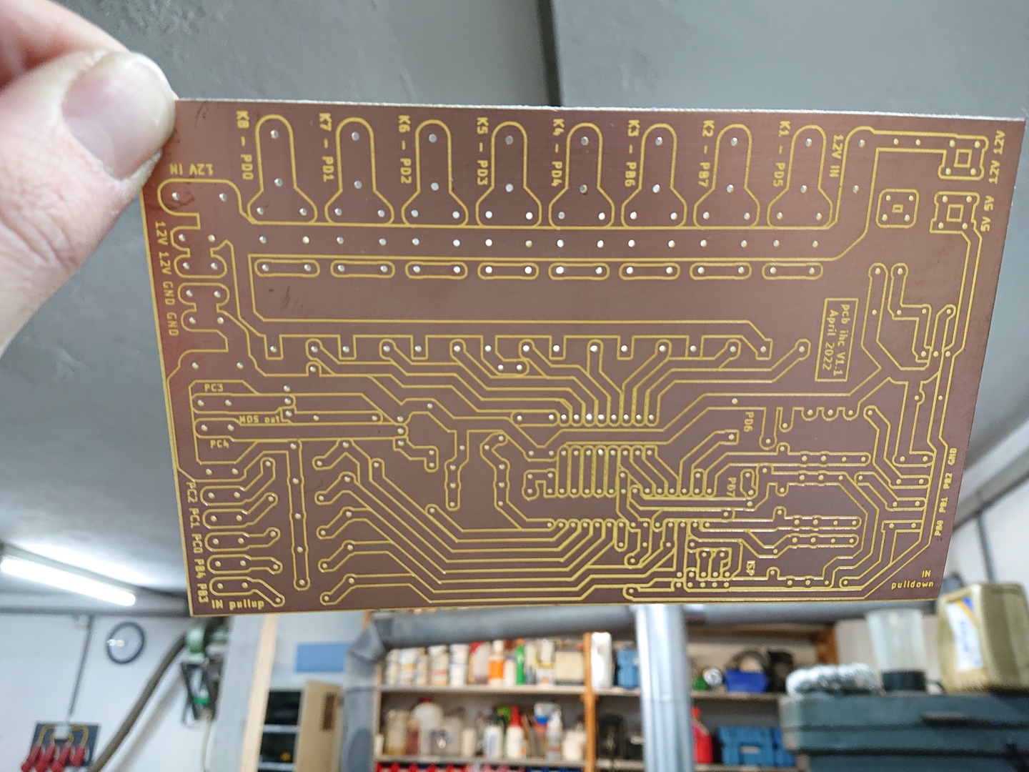
Isolation milling
Instead of sending the files to a professional PCB manufacturer, I decided to produce it myself using the isolation milling method.
Steps
- Export Gerber files from layout software (KiCad / PcbNew)
- Convert Gerber files to G-code for CNC Machine (pcb2gcode)
- Mill a plane slot into wood, for alignment
- Fixate raw PCB using screws in free areas
- Drill holes using 0.8 and 1 mm cutters
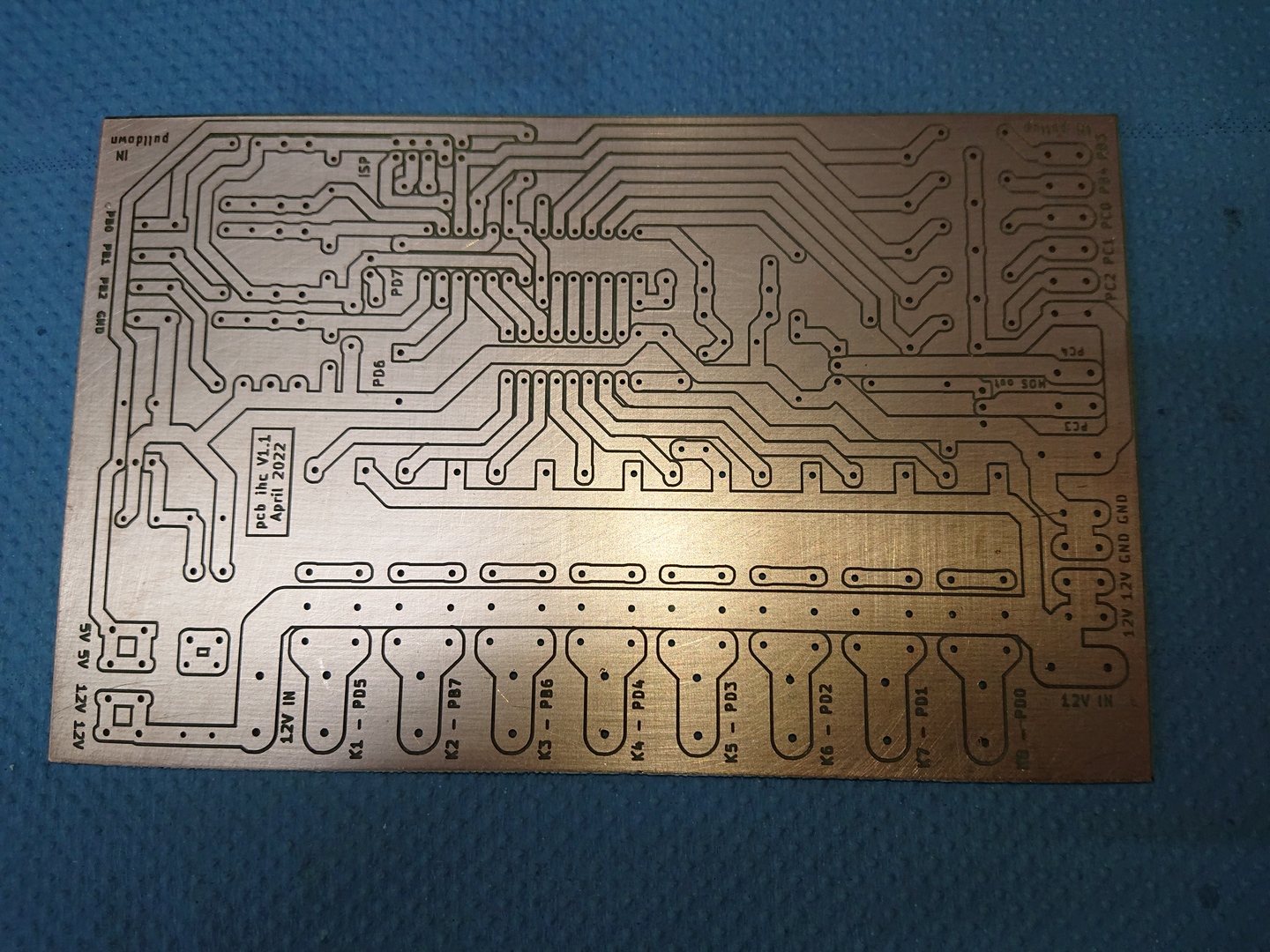
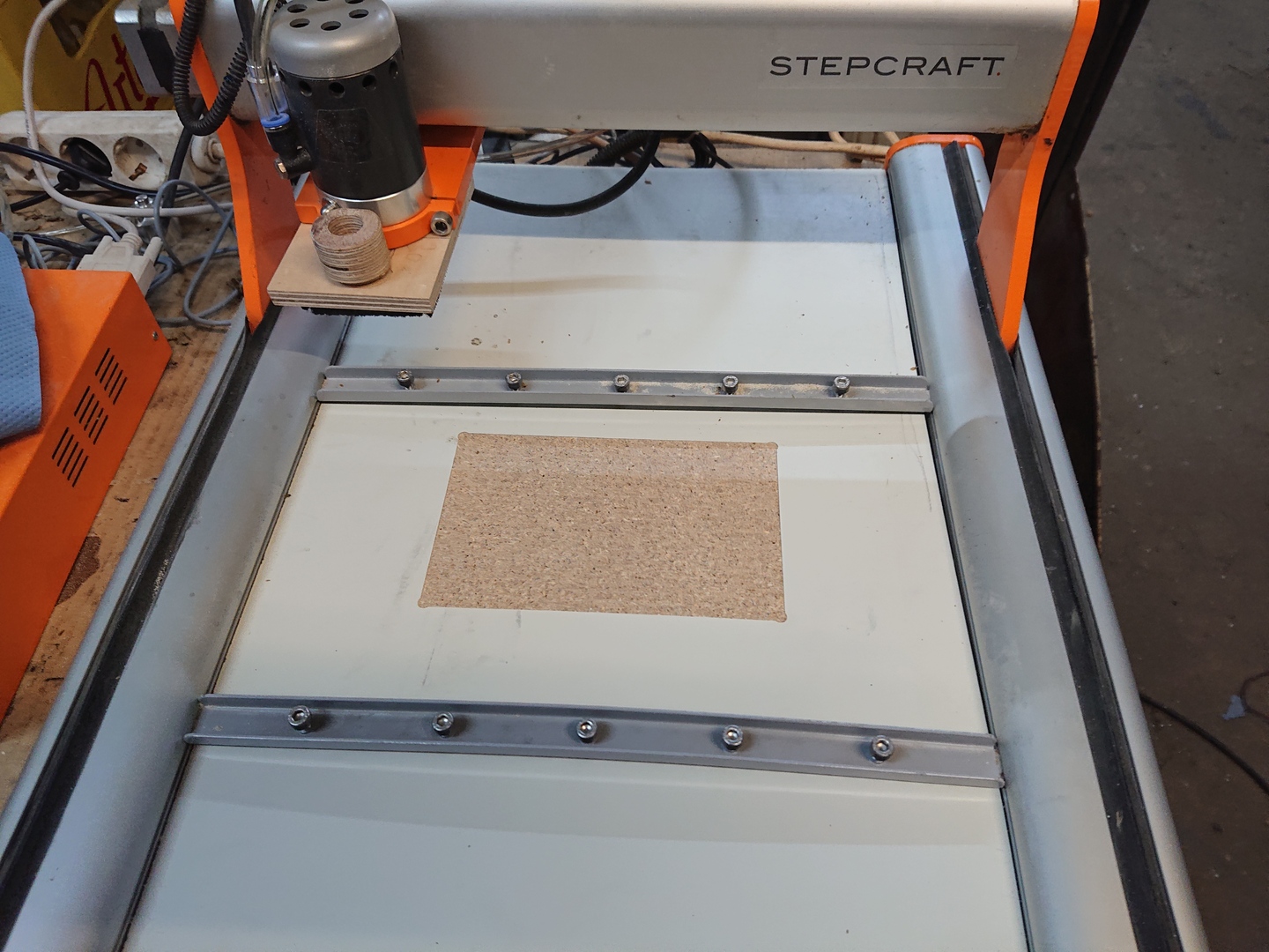
- Isolation milling using a 60 degree engraving tool
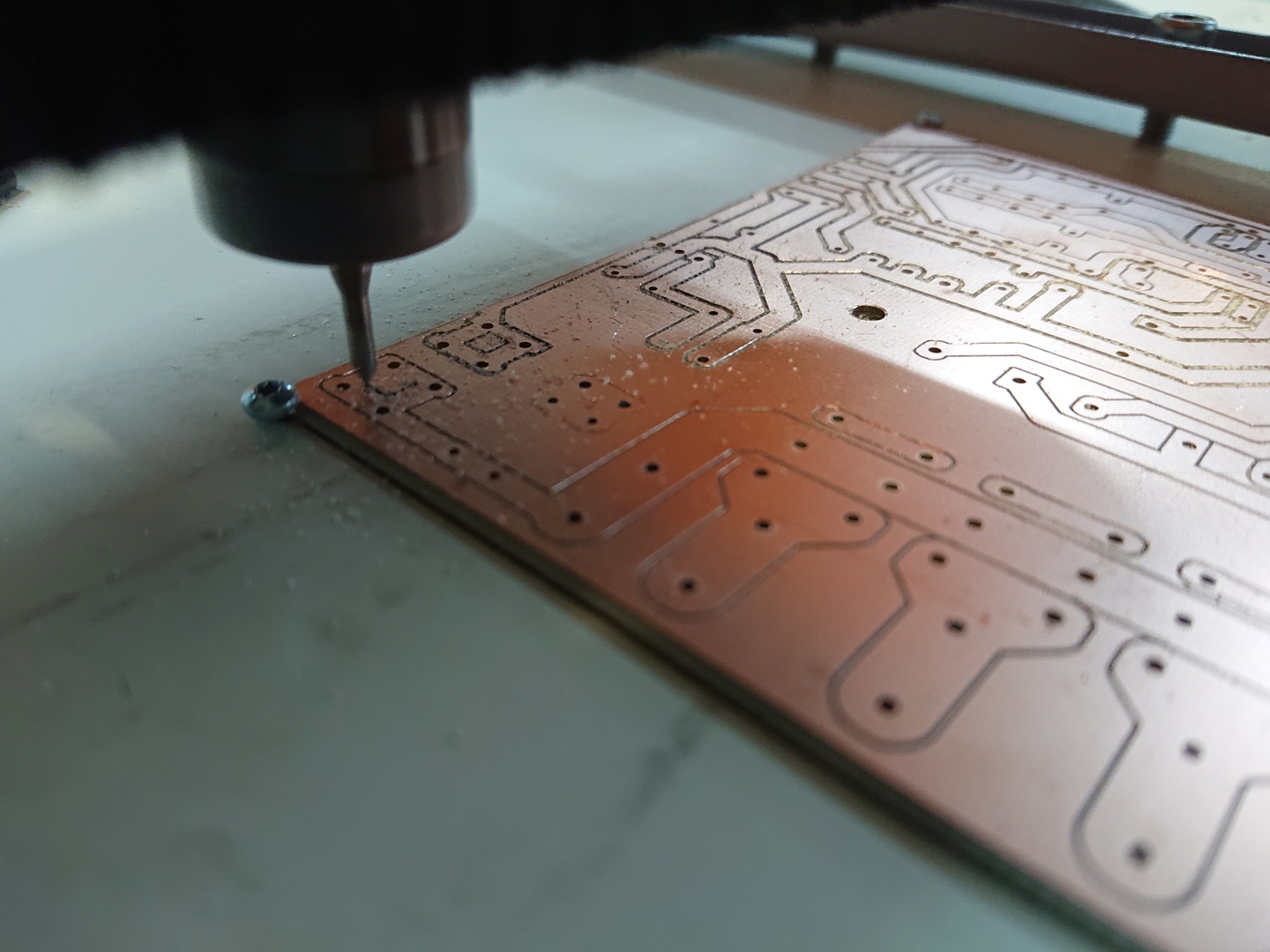 Isolation milling
For more detailed instructions and experiences, refer to the PCB repository.
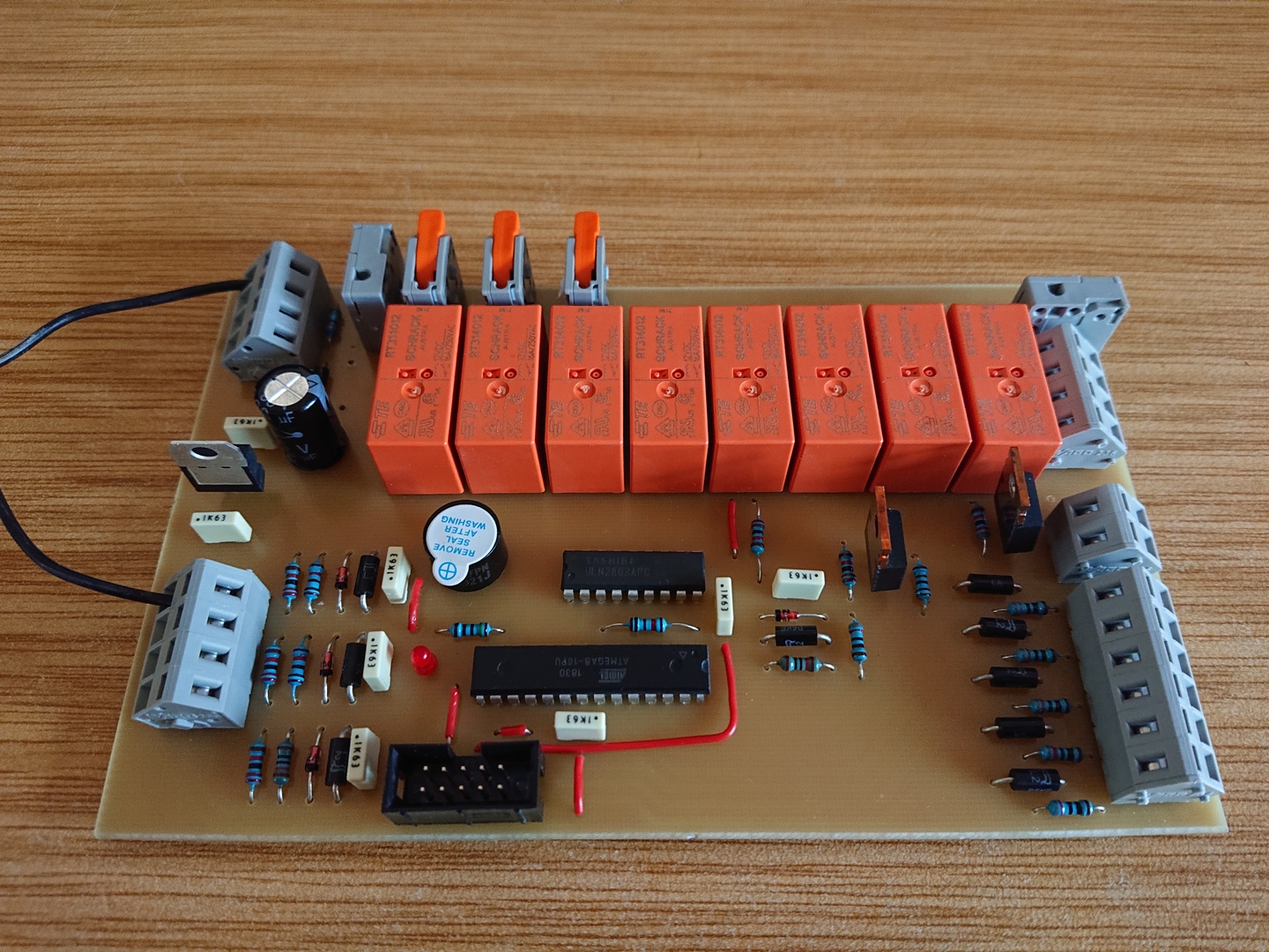
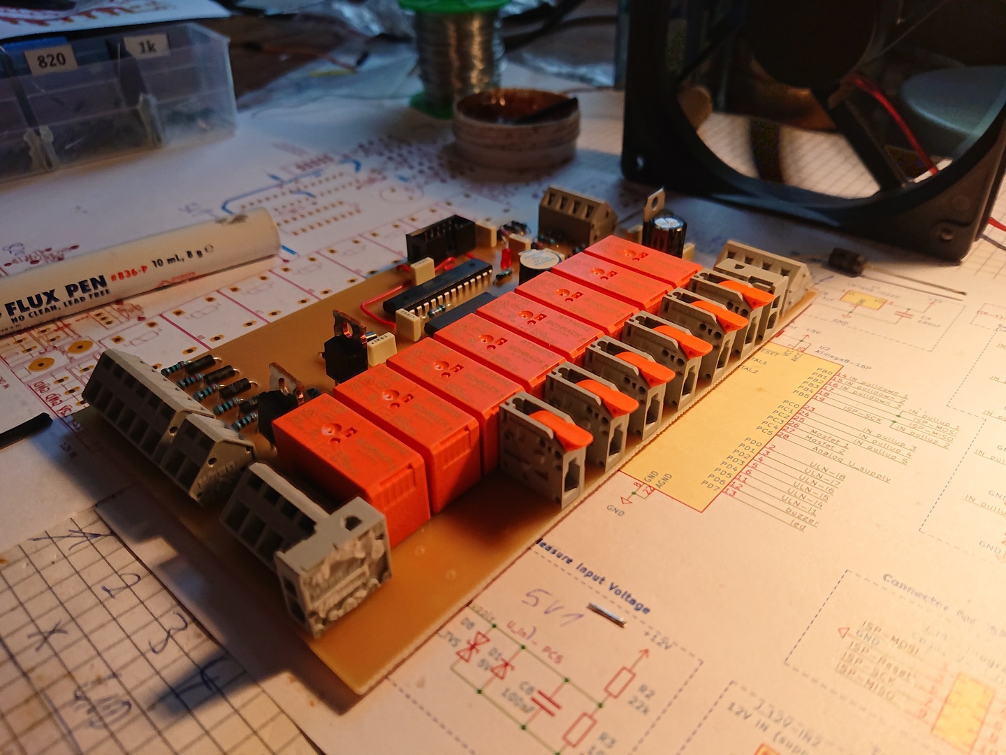
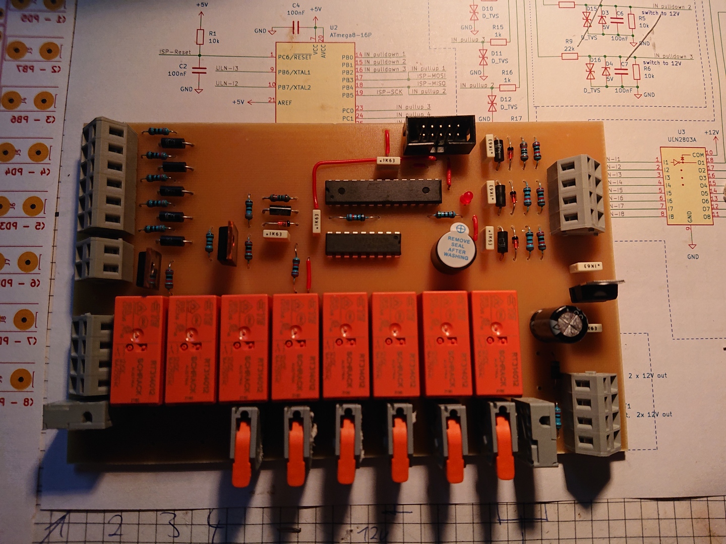
Assembly
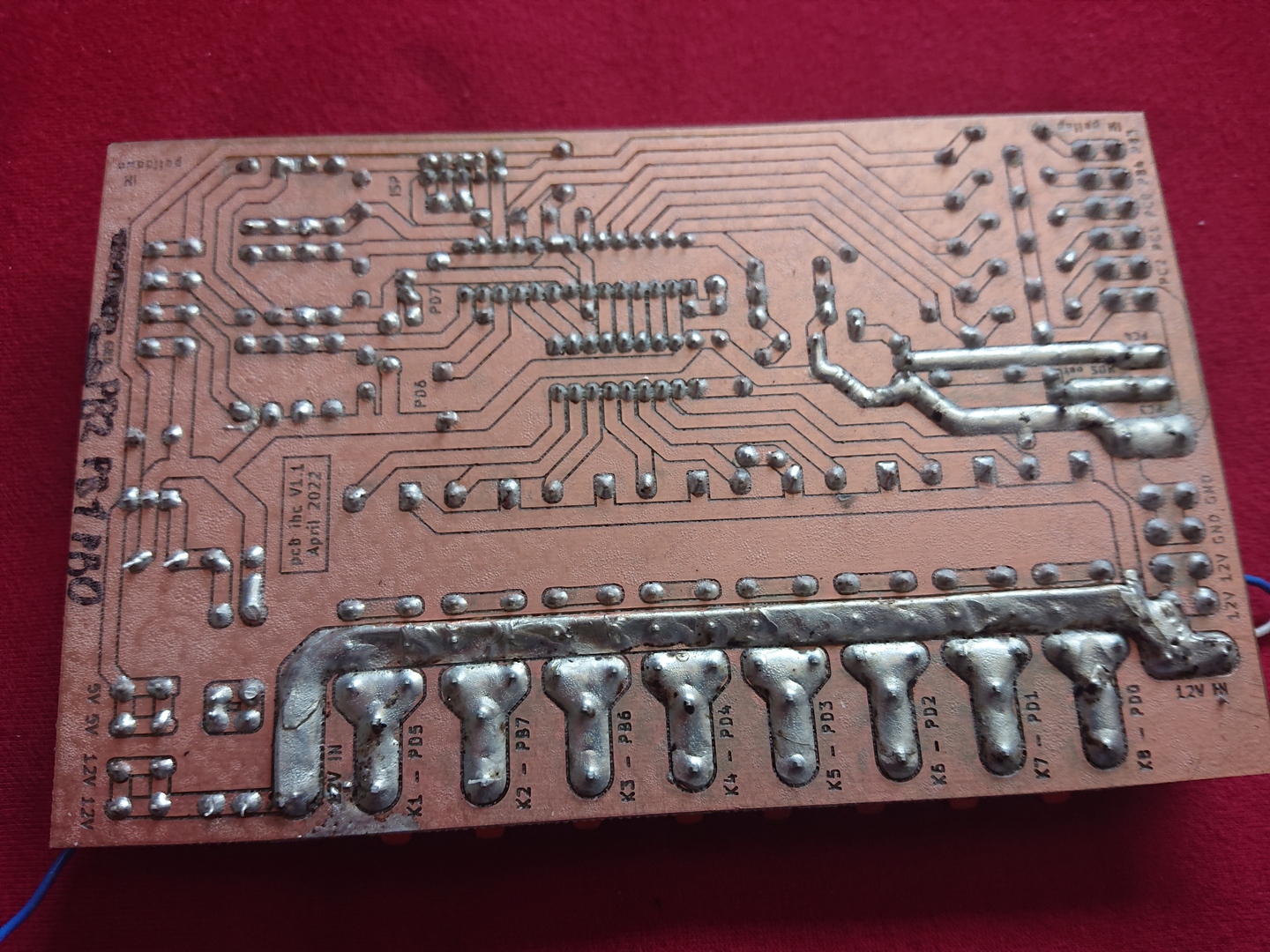
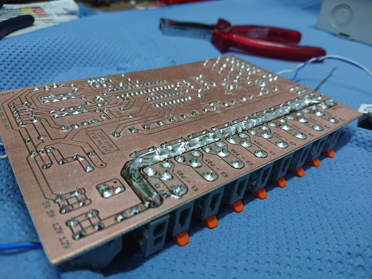
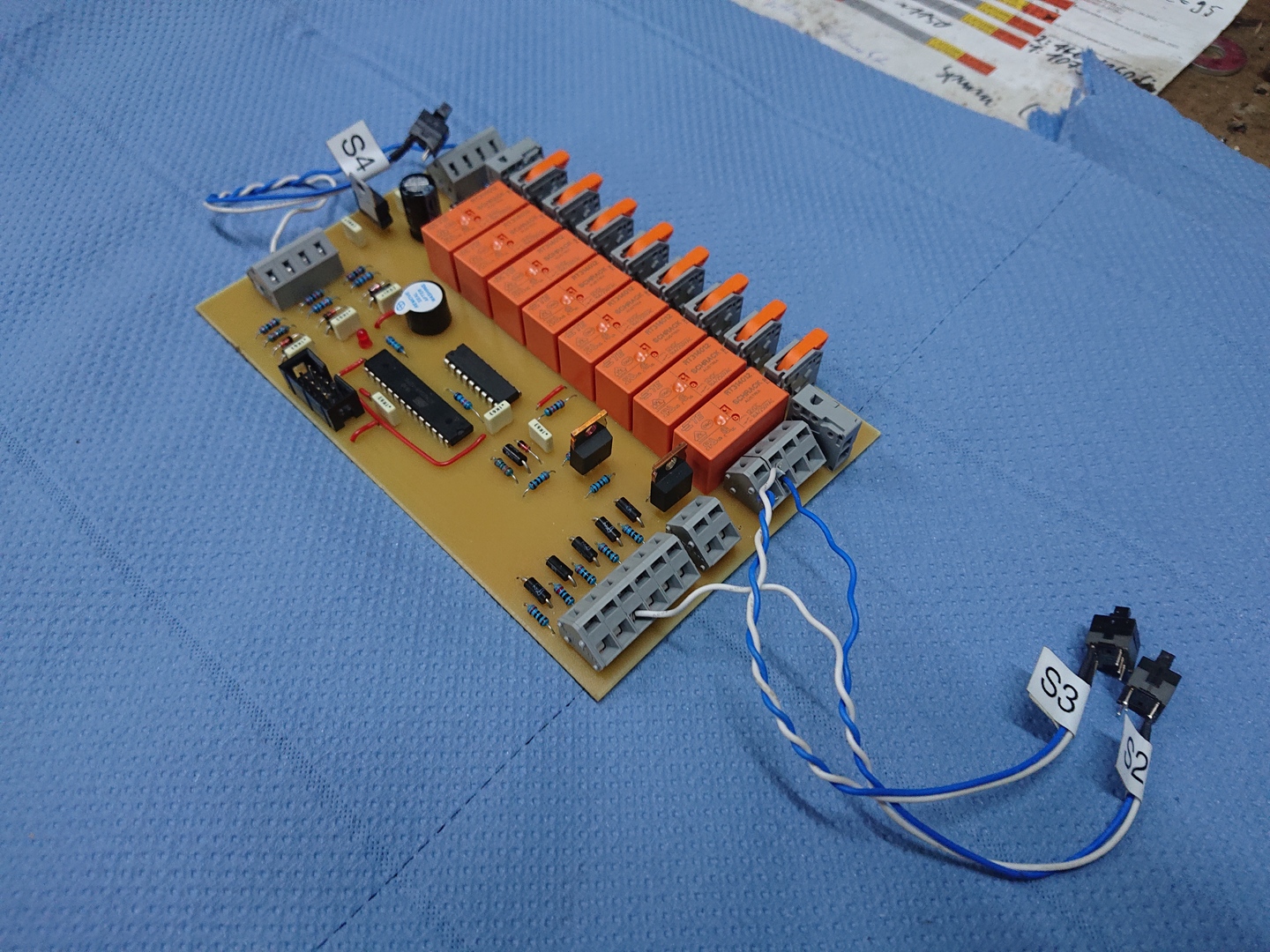
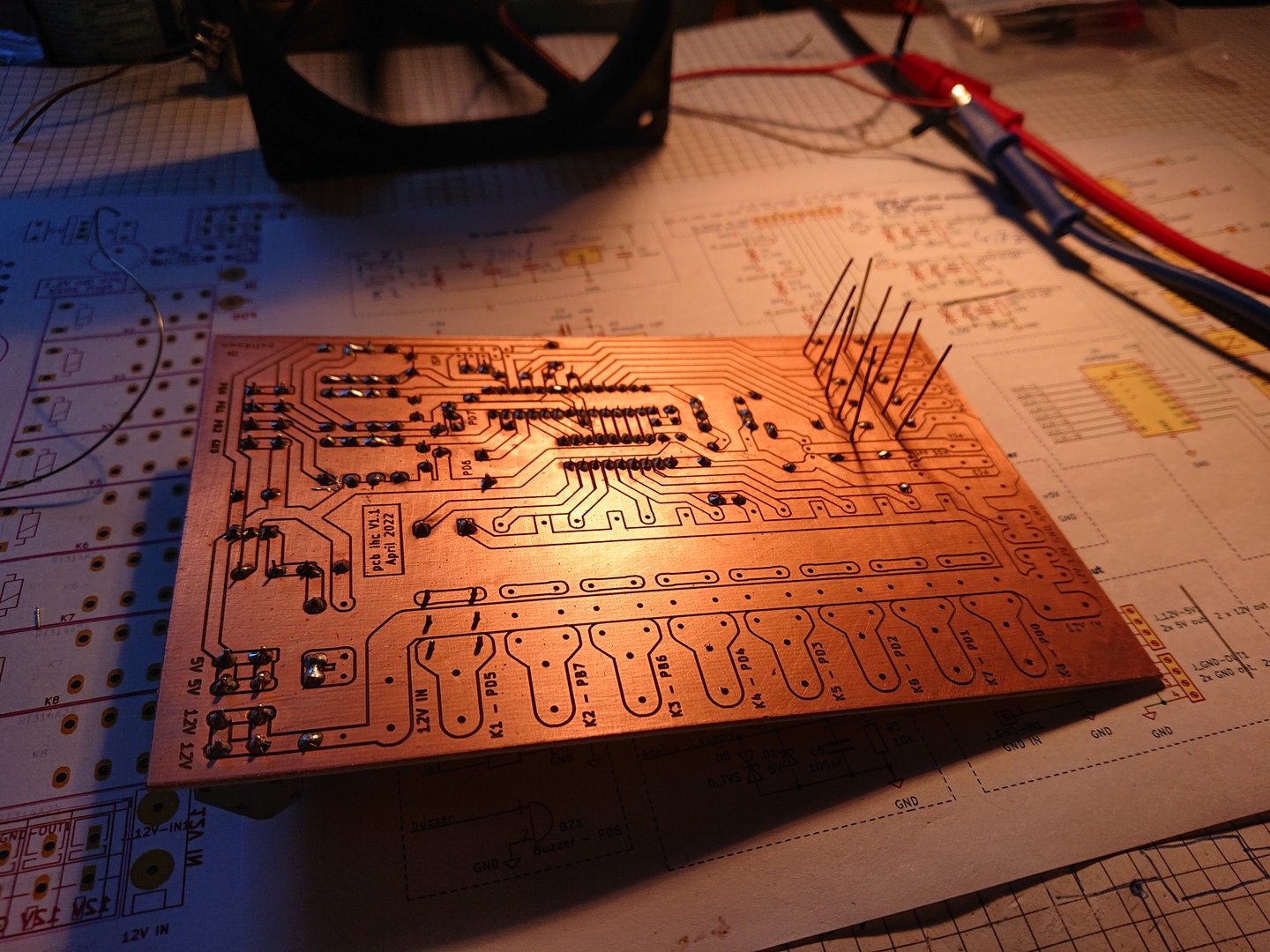
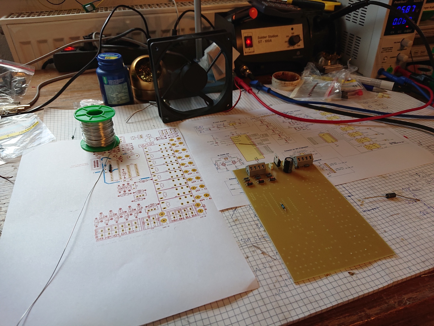
Soldering
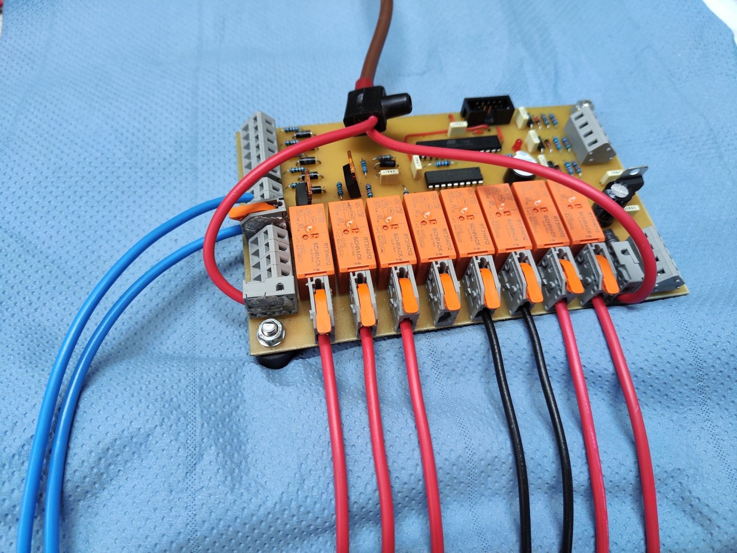
With the help of the layout and schematic the correct components can be soldered onto the pcb.
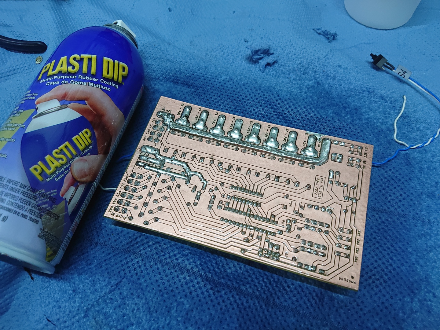
Finish
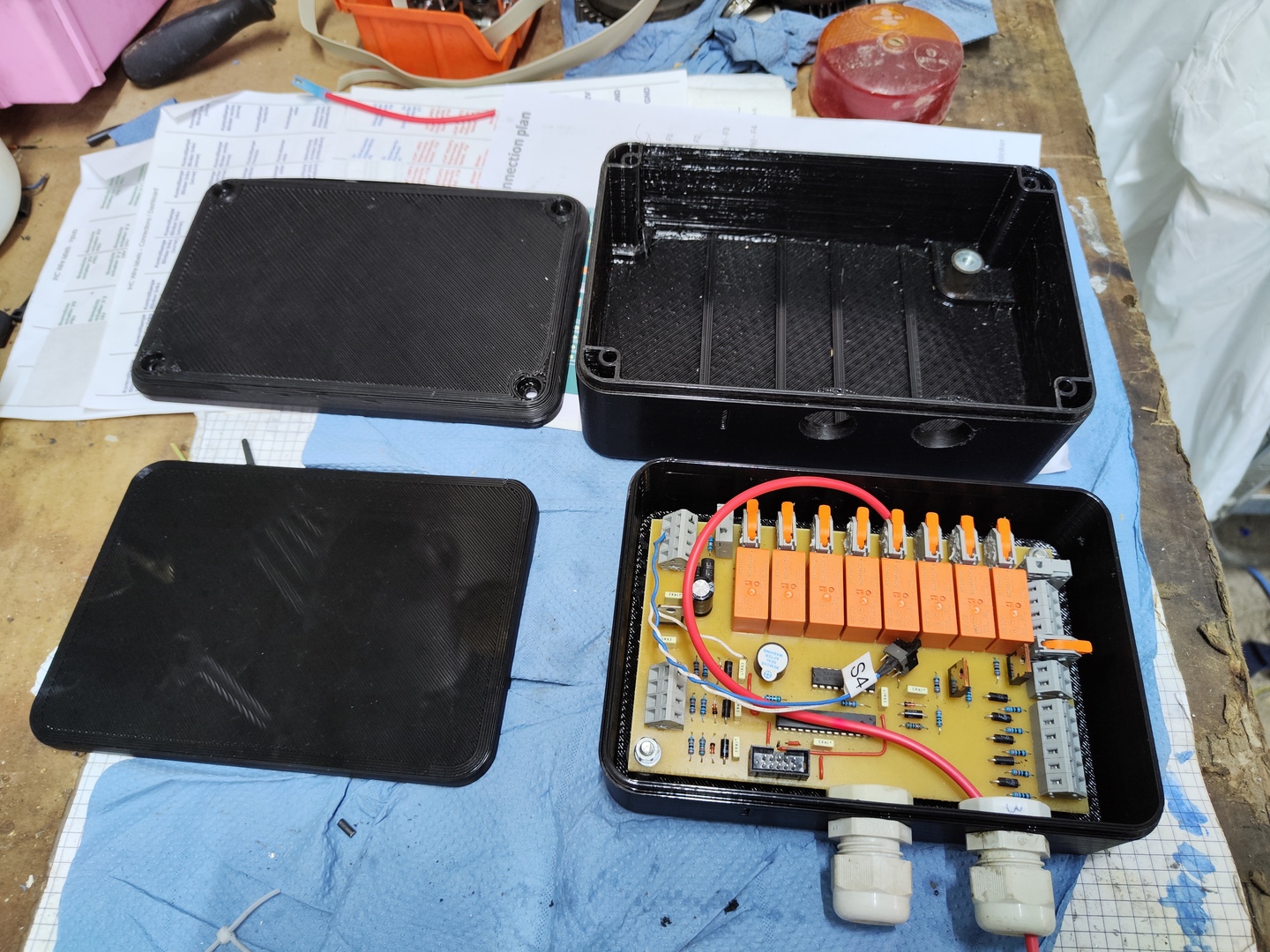
After all the components were soldered, evaluated and the first test was successful, the back side of the board was coated with a plastic layer for insulation and protection against corrosion.
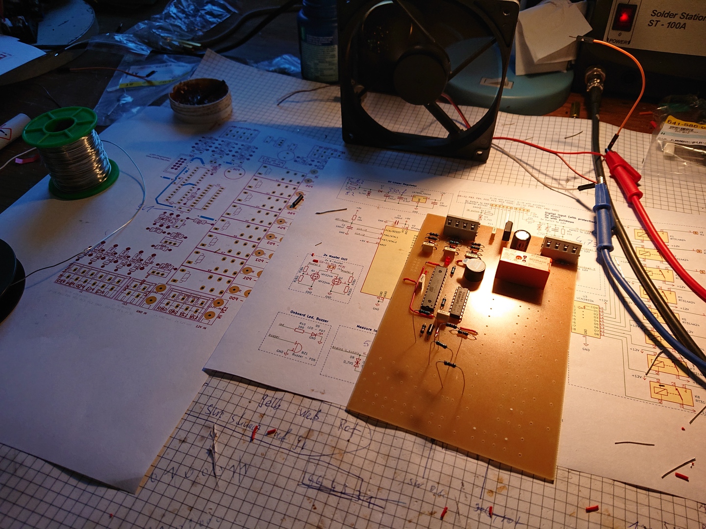 Soldering
Programming
The firmware for this pcb was programmed using the following components:
- C++ and C: Programming languages
- GCC: Compiler
- Cmake: Software for controlling the compilation process
- AVRDUDE: Software for flashing the Atmel AVR microcontroller
- USB ISP Programmer: Hardware used as interface between pc and pcb
The source code is available on GitHub.
Installation
In order to integrate the created pcb into the tractor, the following steps were executed:
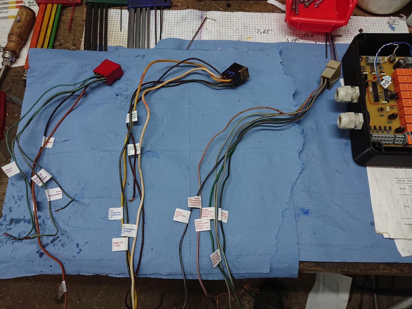
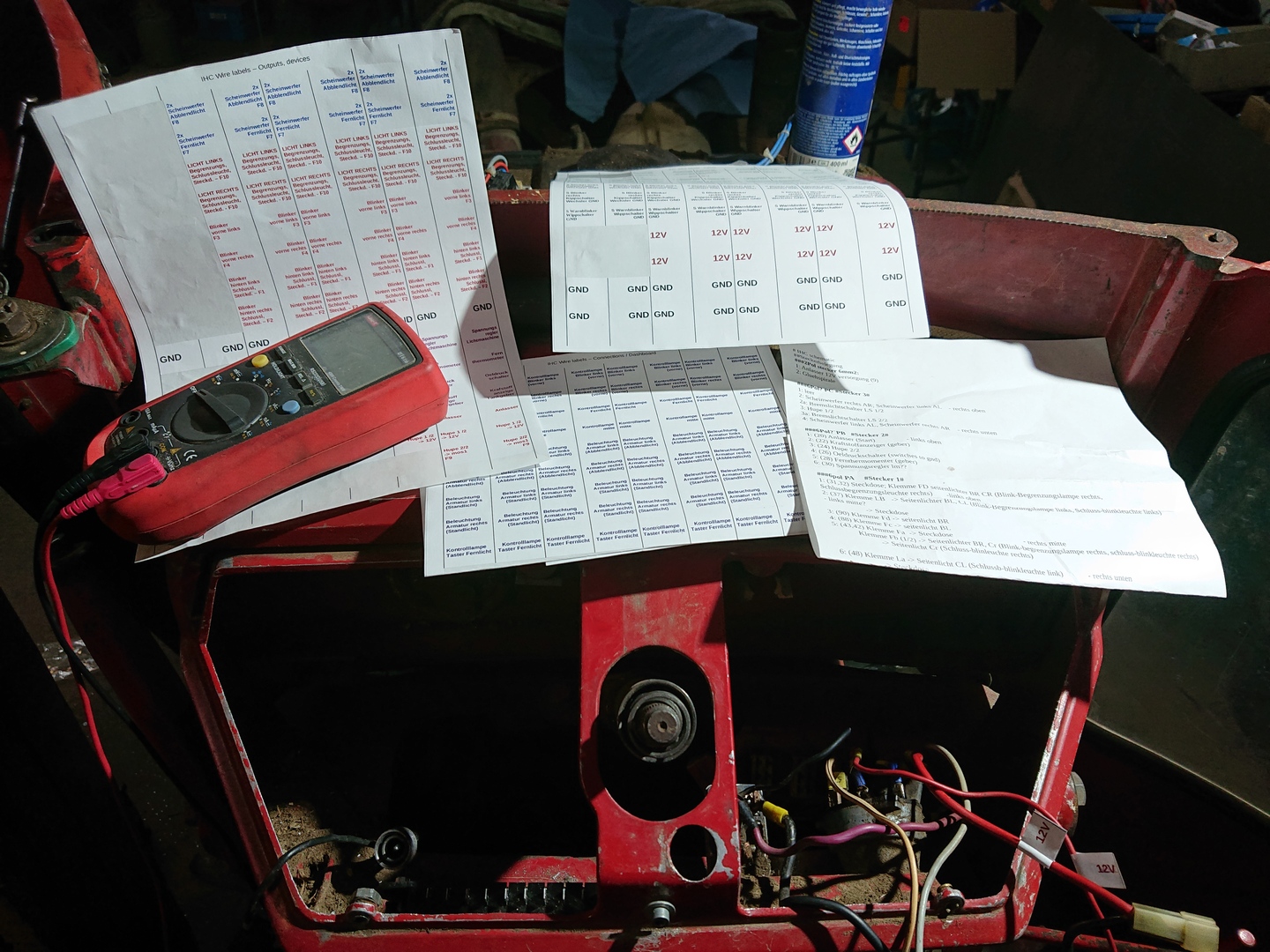
- Identify and label the present wires
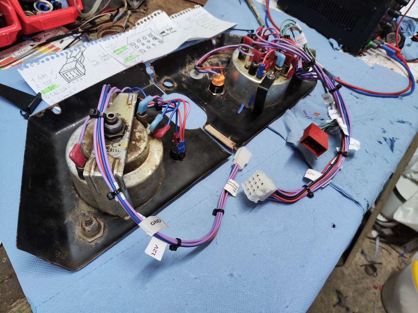
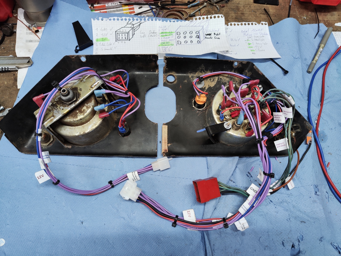
- Rewire the two dashboard panels
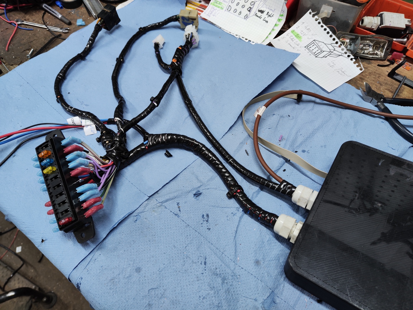
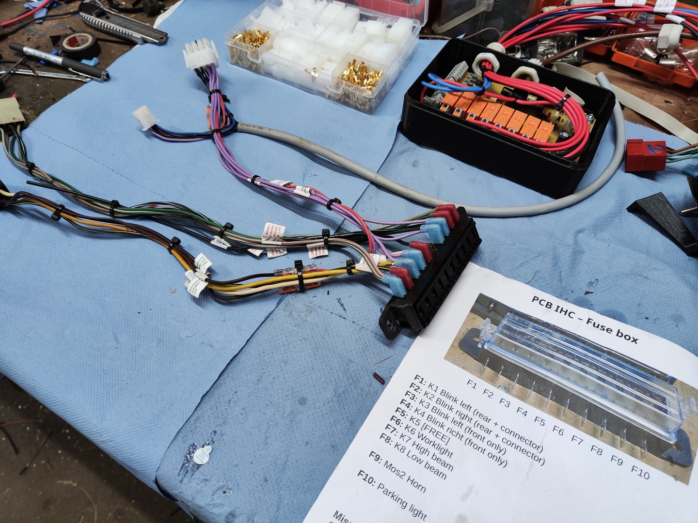
- Create wire harnesses with new and existing connectors
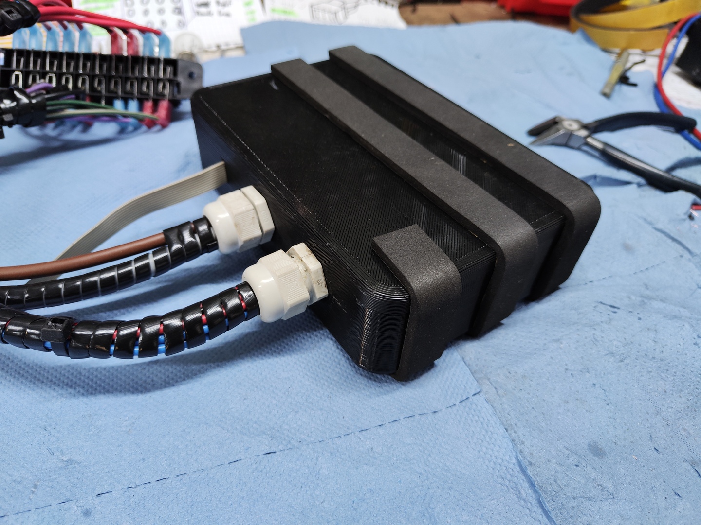
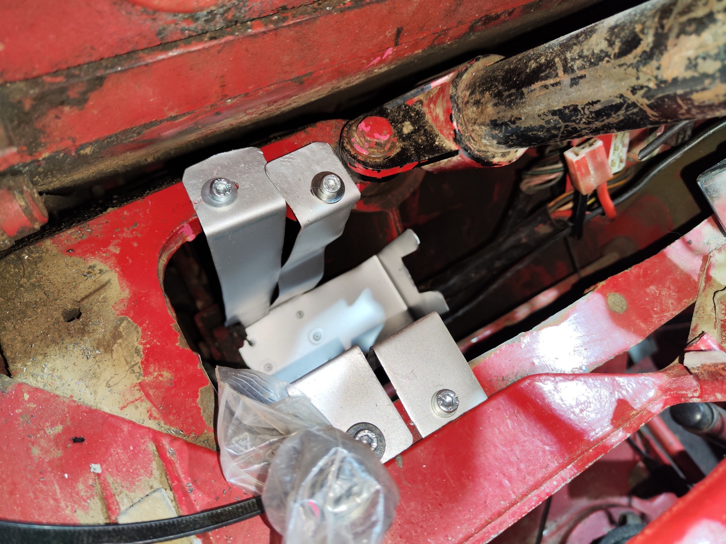
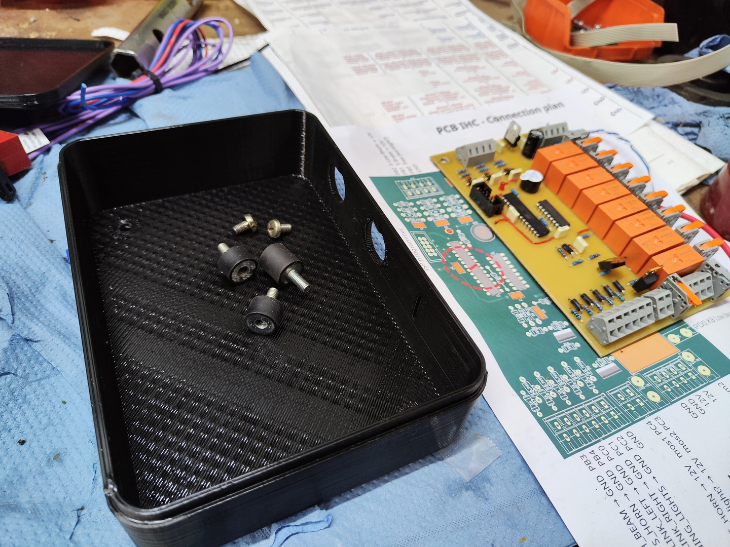
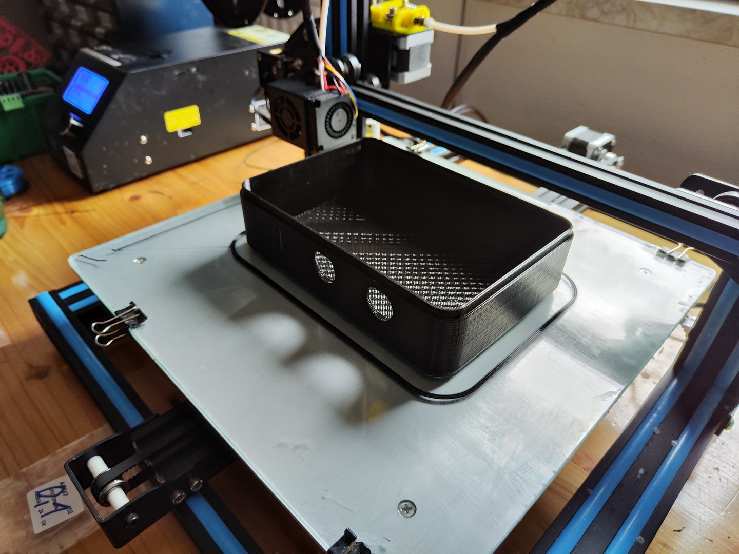
- 3d-print a housing
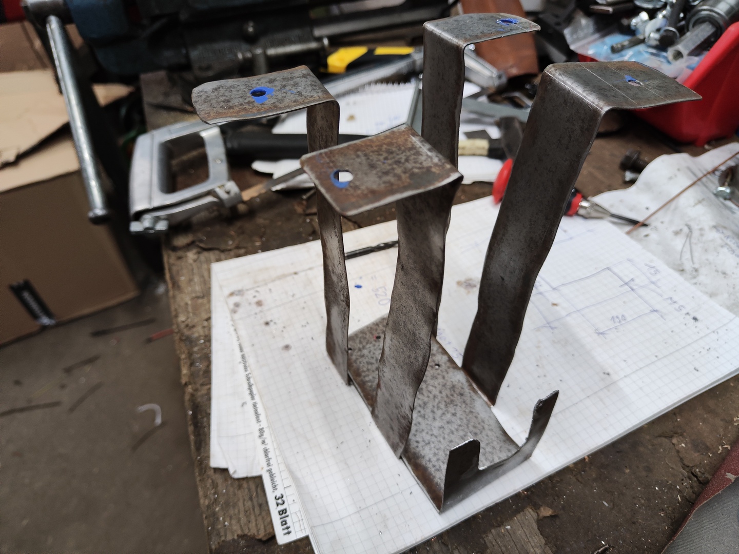
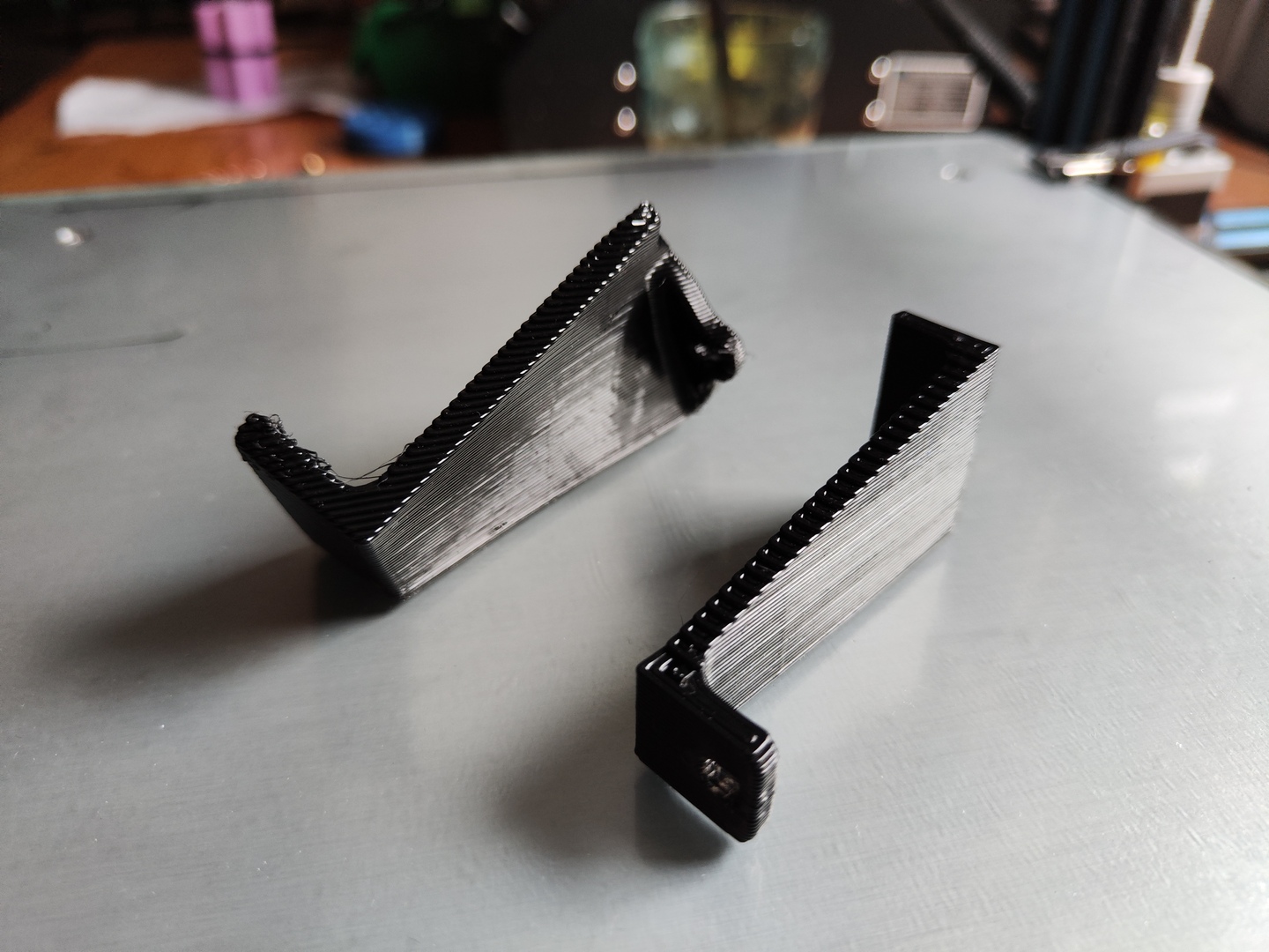
- Build a bracket to mount the housing in the tractor
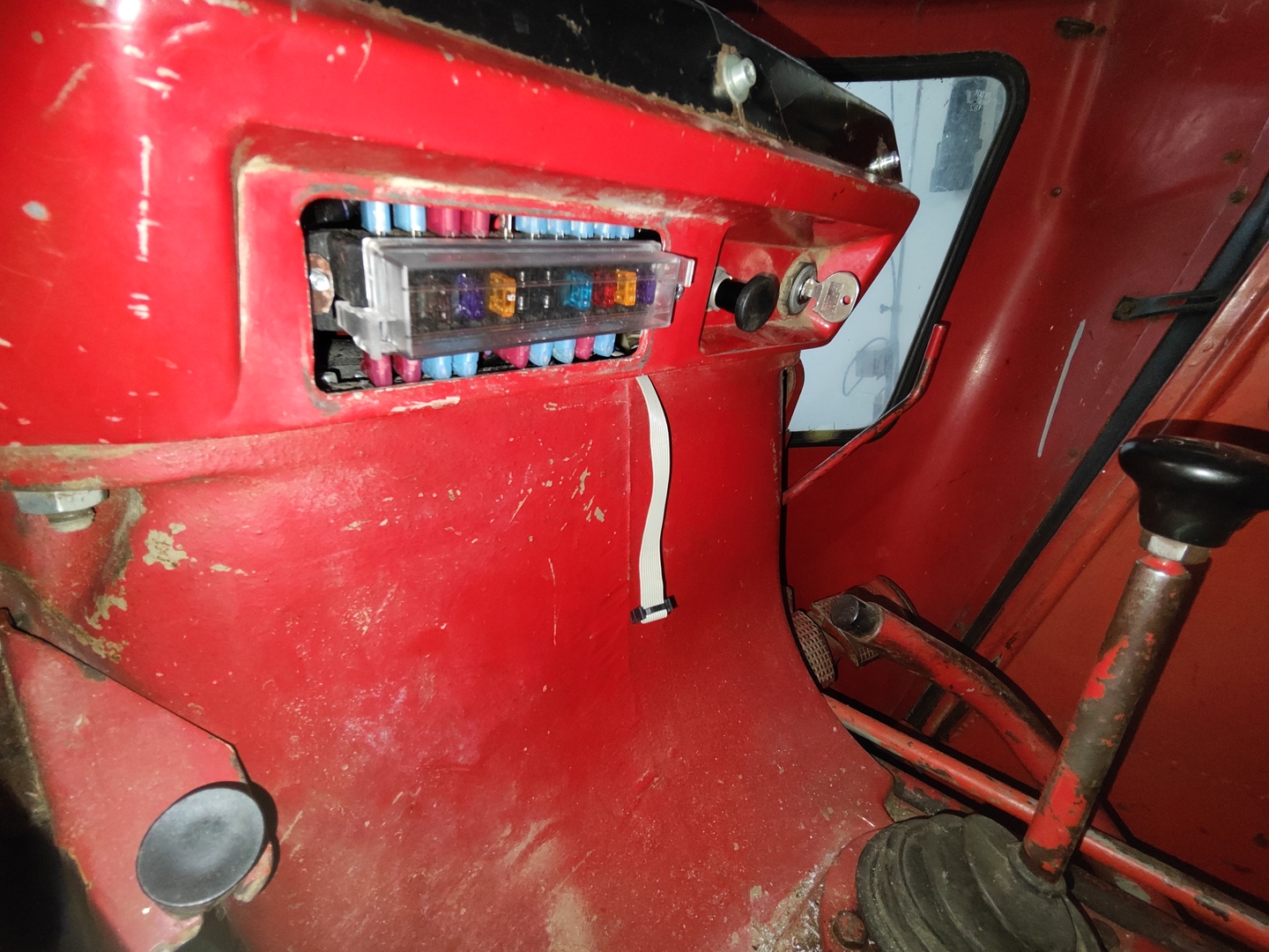
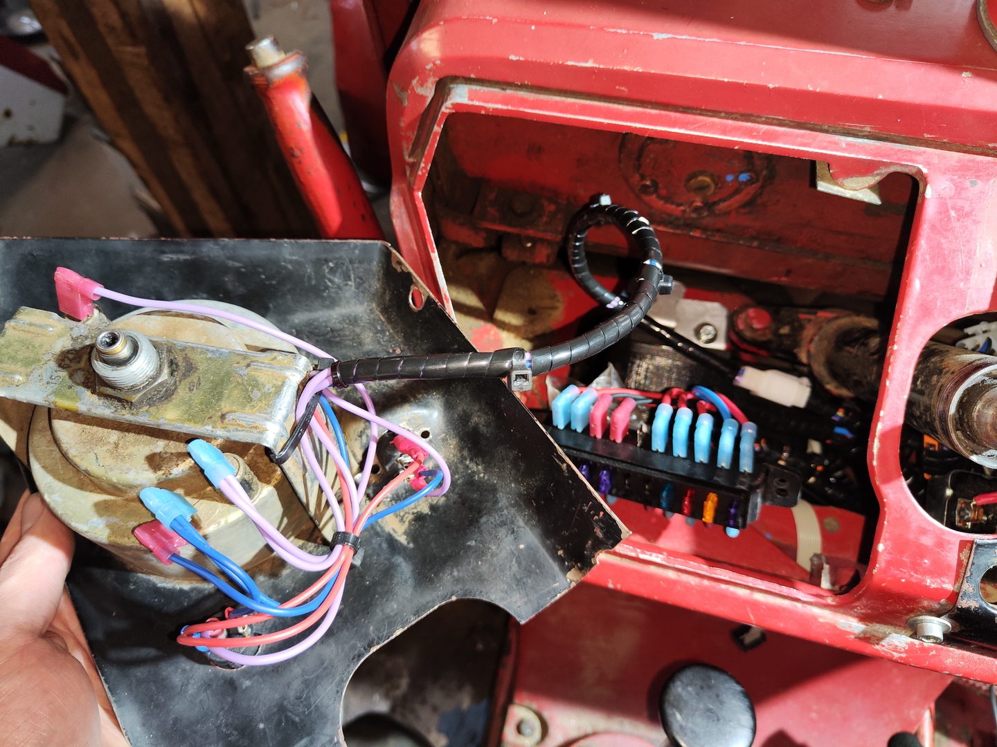
- Integrate a new fusebox
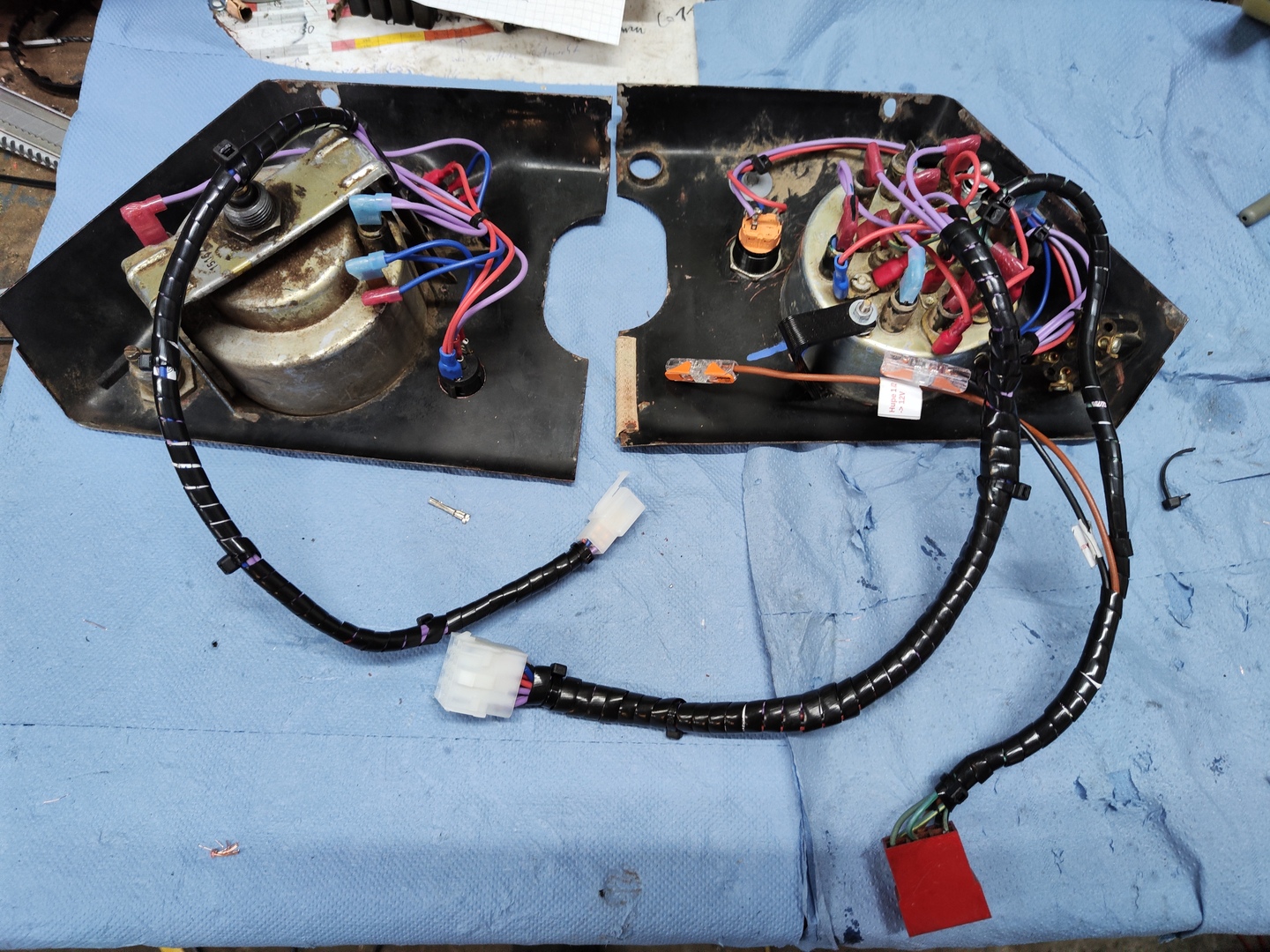
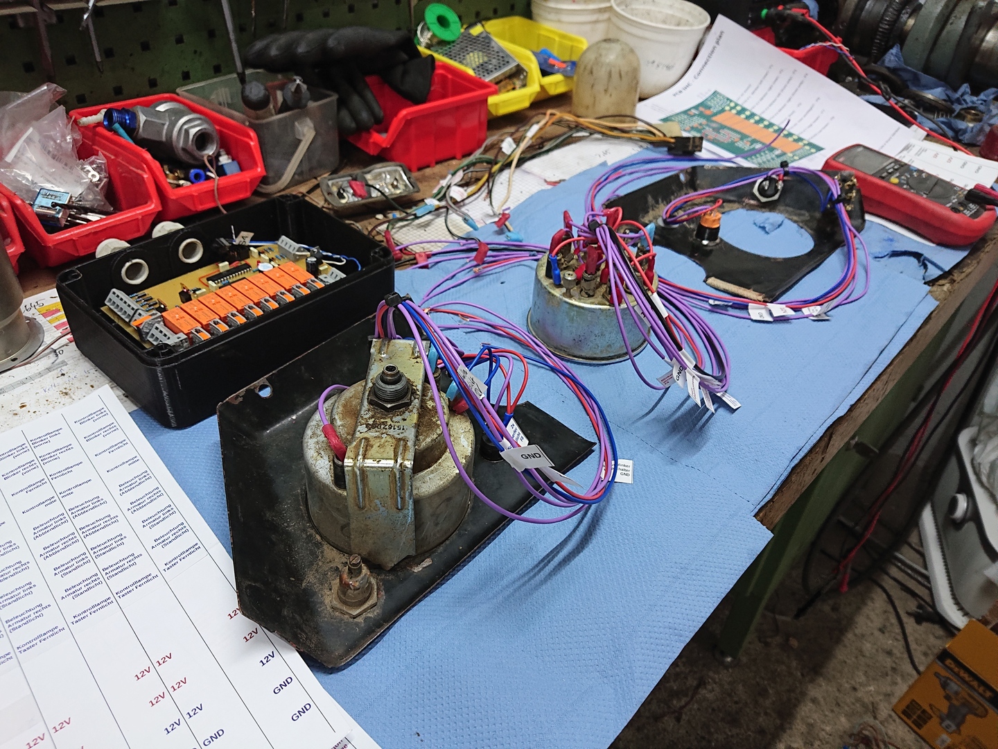
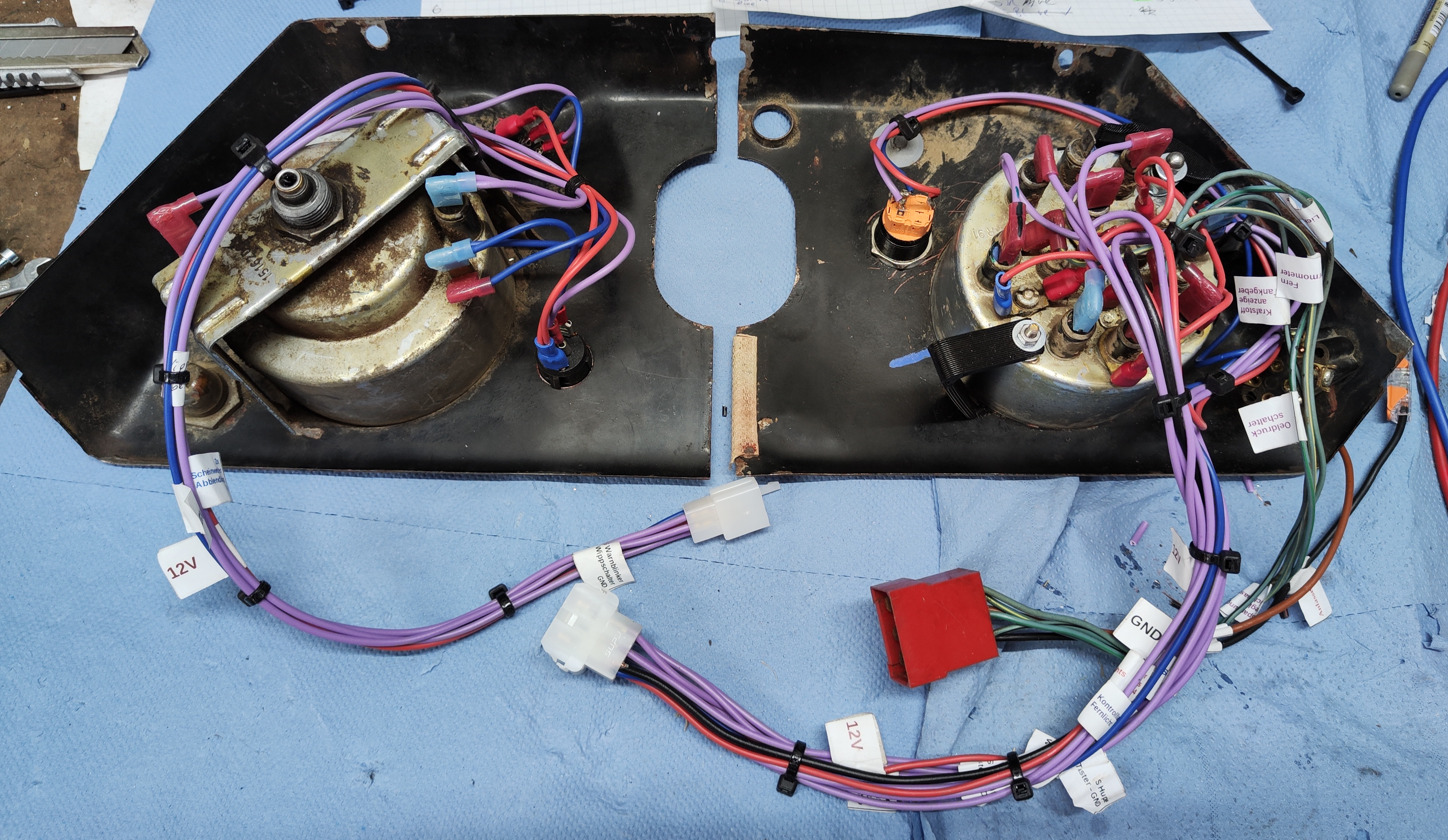 Bottom side of rewired dashboard panels
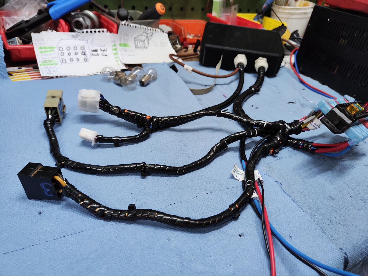
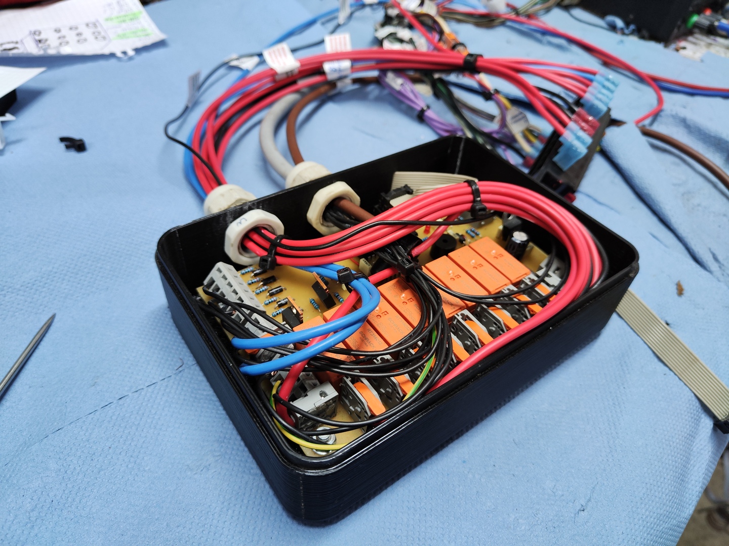
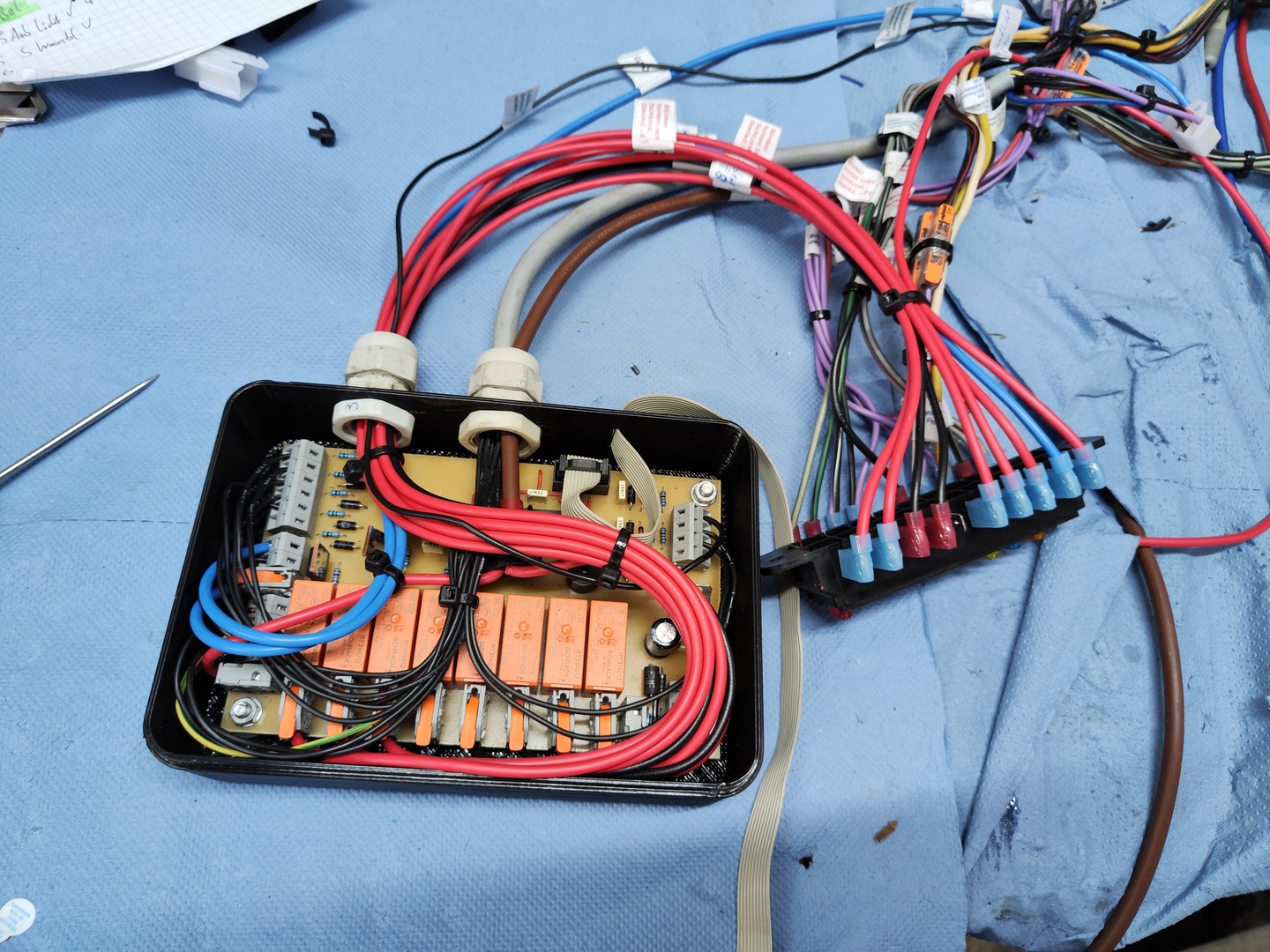
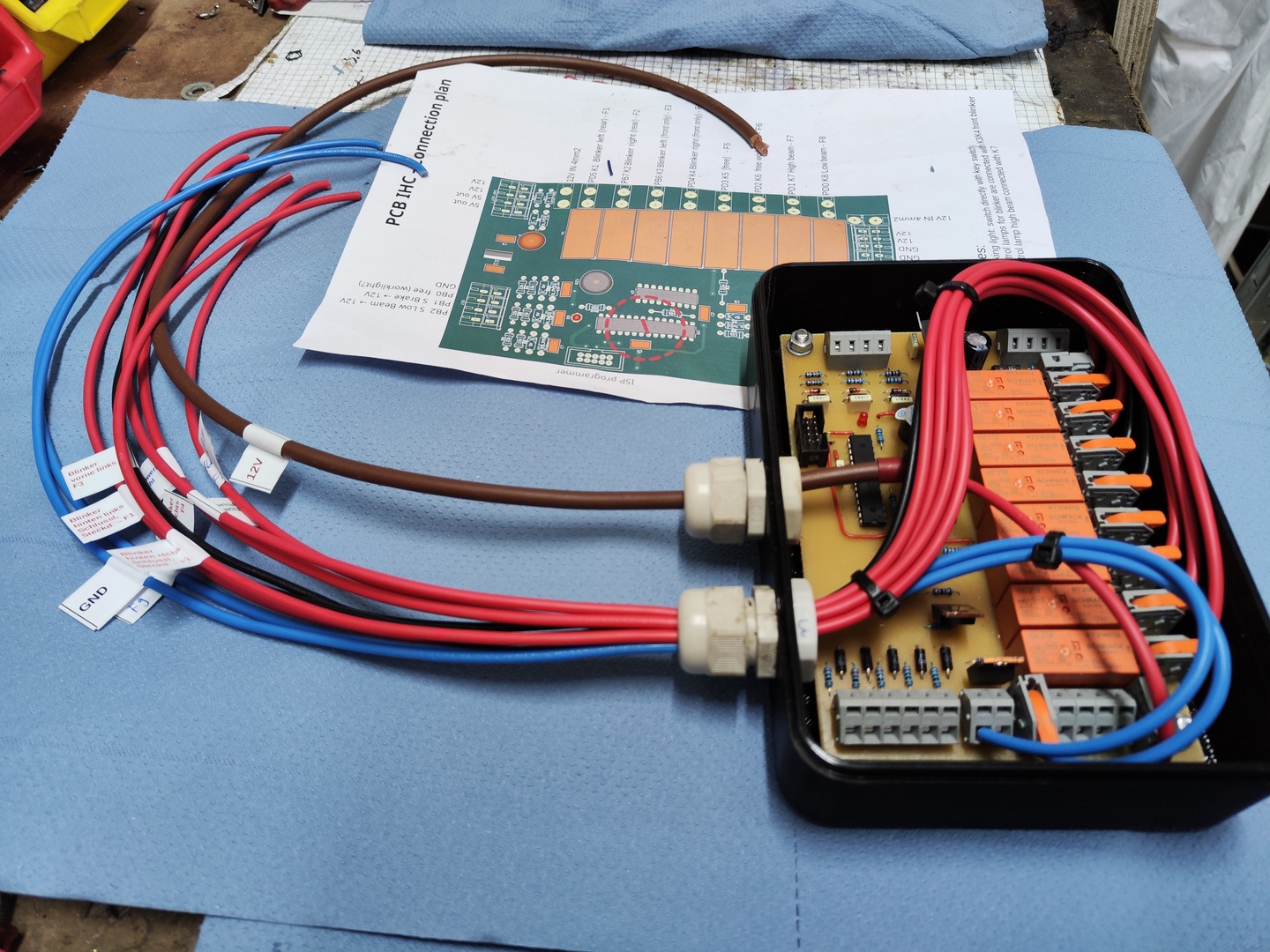
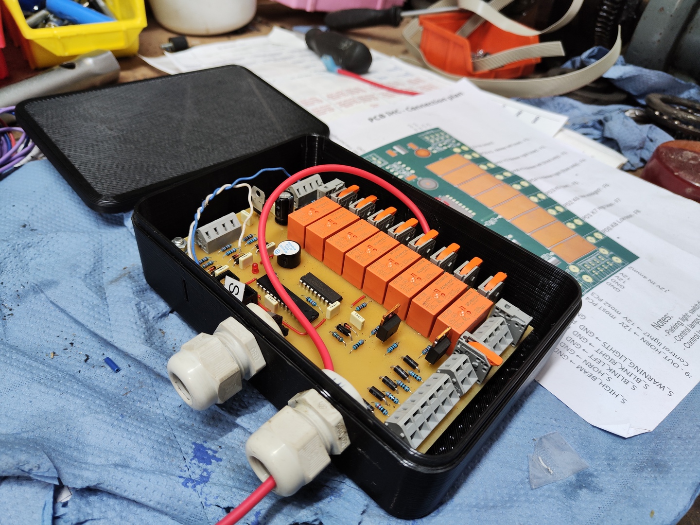
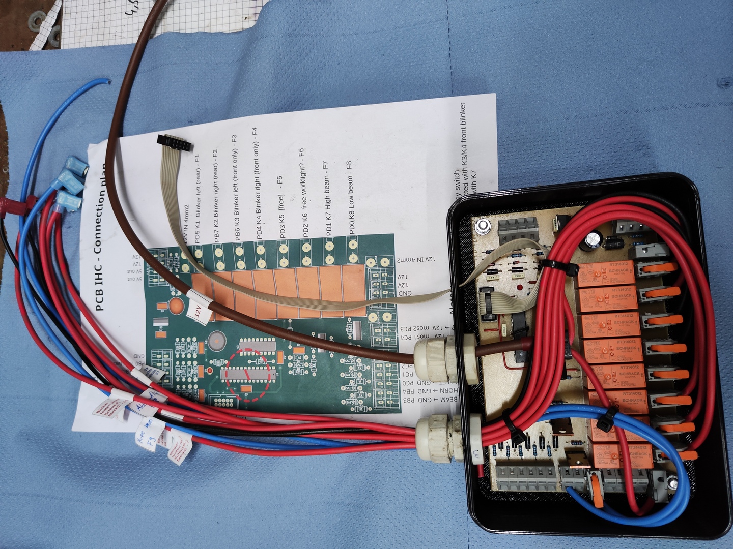 Wiring the pcb according to plan
Videos
PCB production
Drilling:
Isolation-milling:
Function test
Front:
Rear:
Gallery