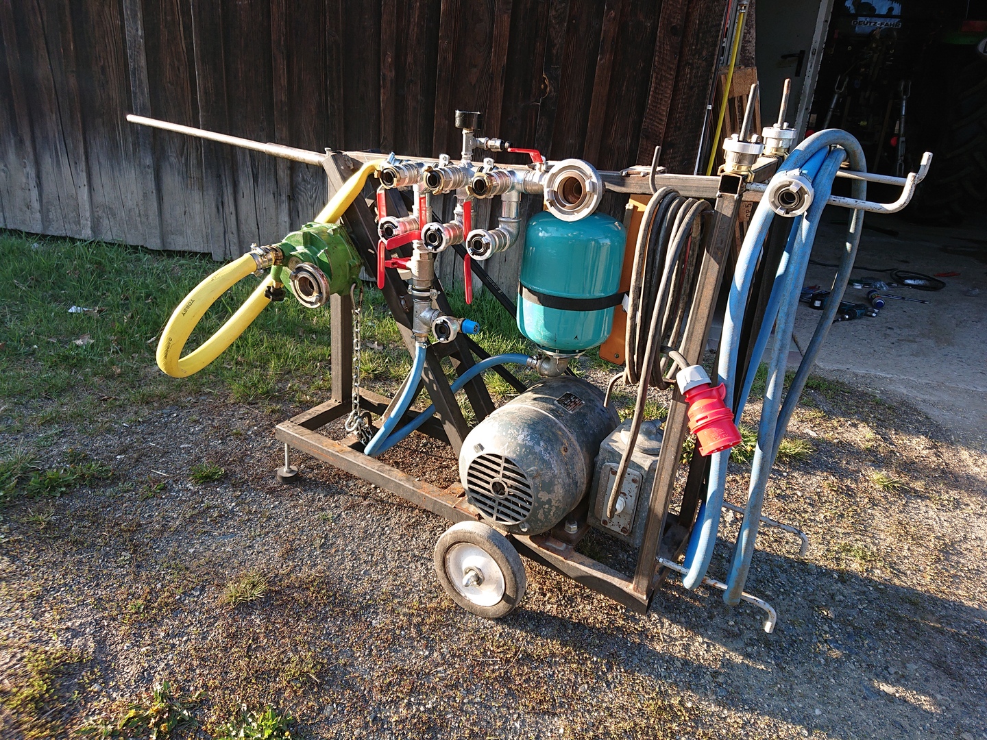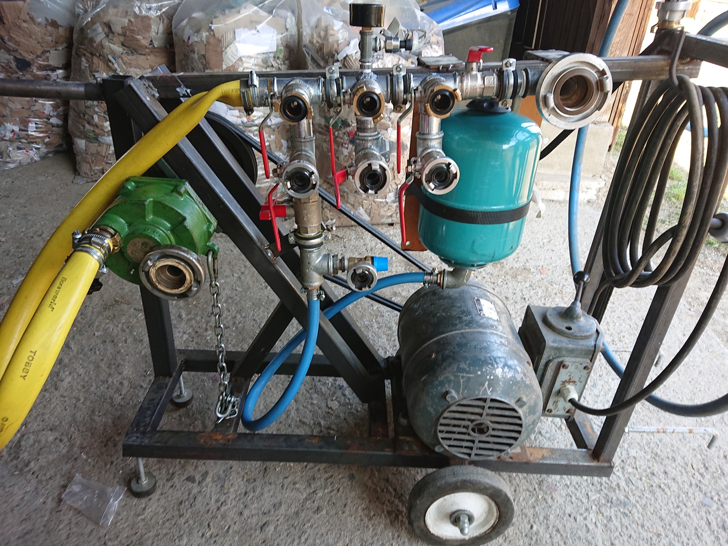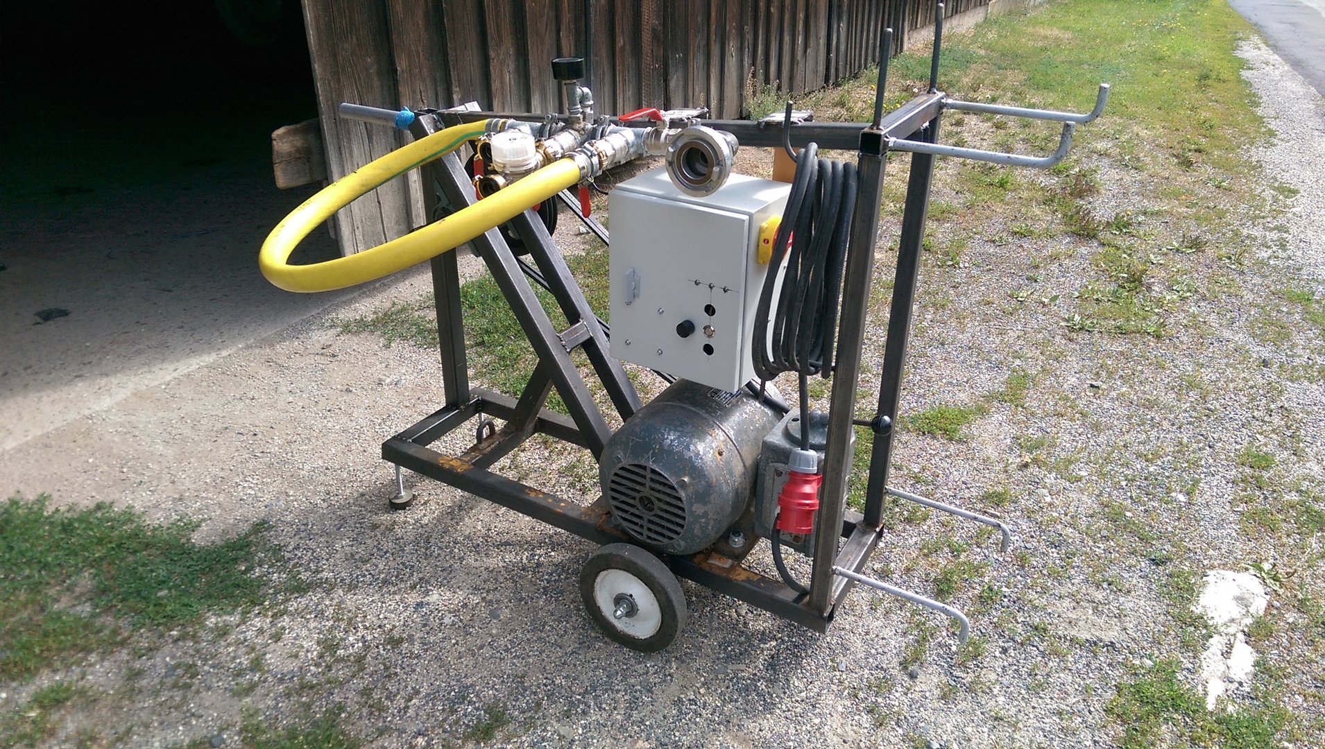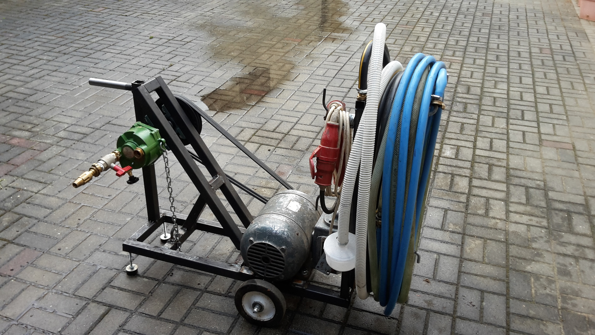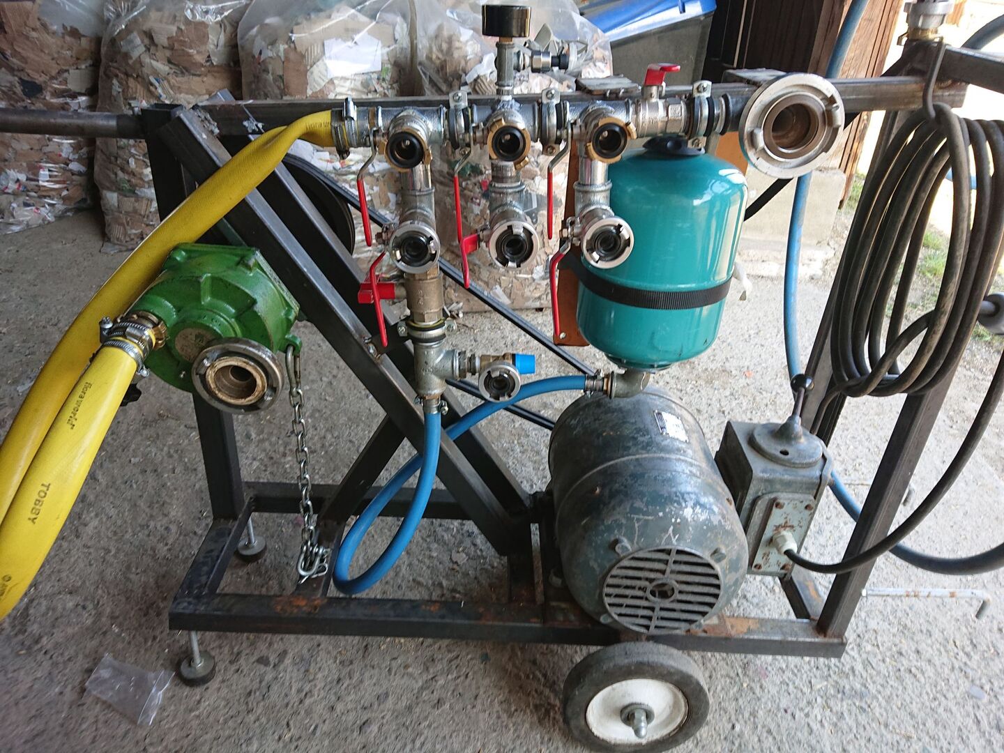
Custom Build with a PTO driven water pump electrically powered and pressure regulated.
This project transforms a PTO (Power Take-Off) pump, intended for tractors, into an electrically driven system. The system features a pressure and flow sensor, with a microcontroller controlling a bypass valve and a 4 kW electric motor.
Reasons for this project
Why choose PTO Pump?
- Enhanced Performance: Significantly higher pressure (typical 25 bar vs 5 bar) and flow capabilities compared to commonly available pump systems
- Versatility: The same pump can still be used with a tractor when needed
Why automate it?
- Noise Reduction: Minimize noise level by operating the pump only as fast as necessary
- Energy Efficiency: Optimize power consumption by reducing motor speed and pressure
- Flexible Control: Microcontroller-driven system allows for easy integration of additional features (e.g. timeouts, remote-control)
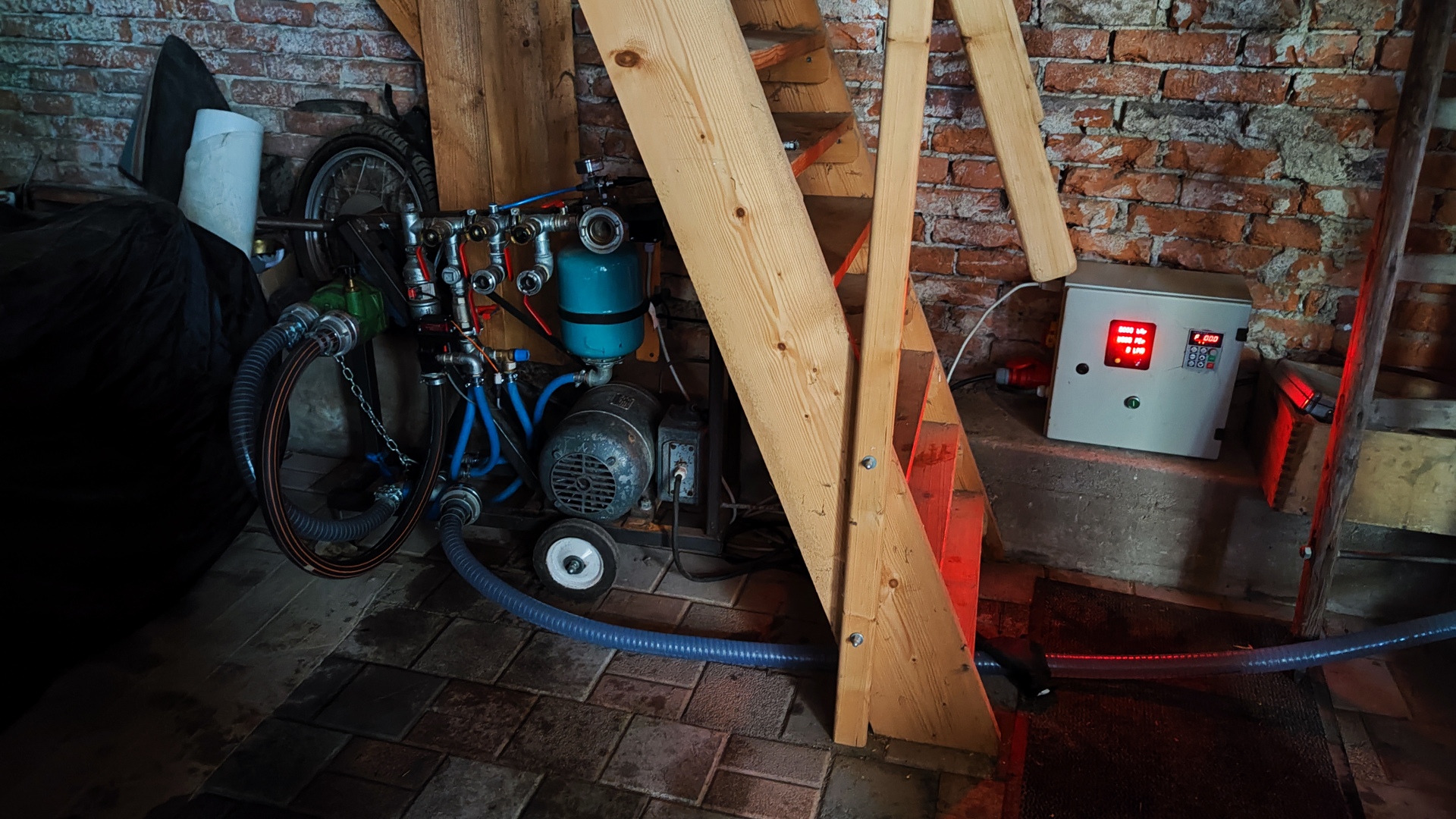
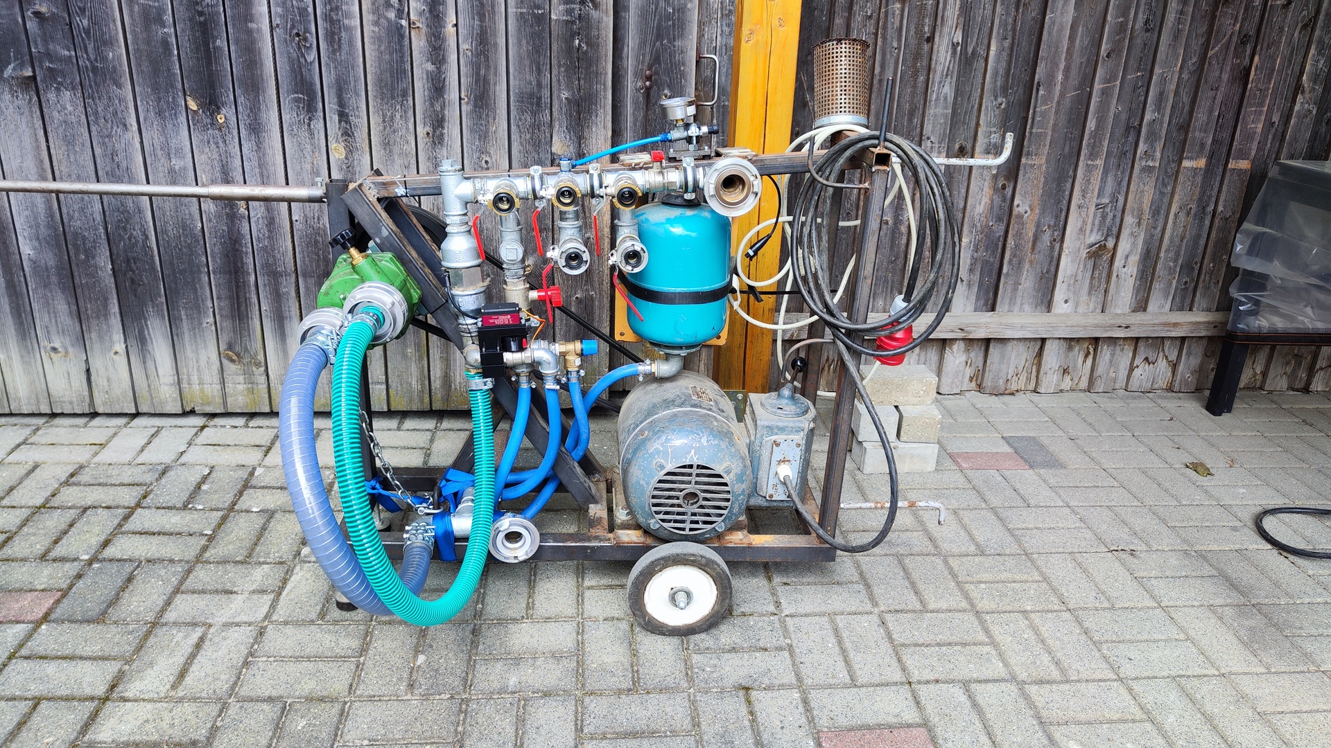
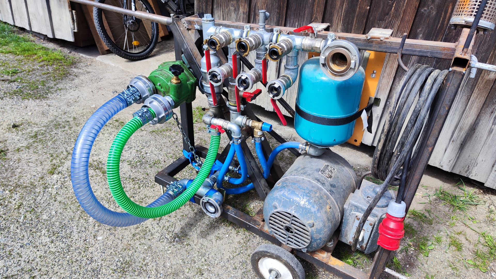
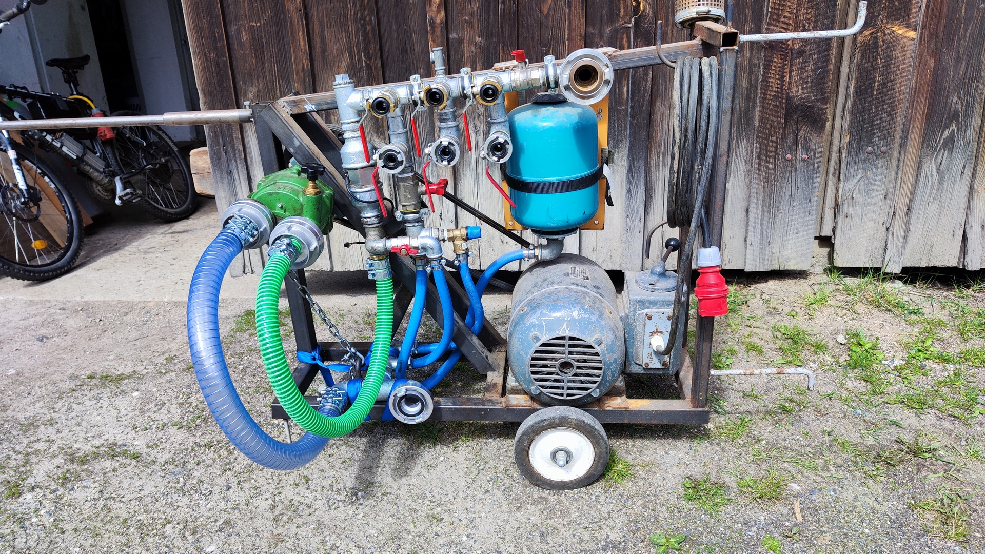
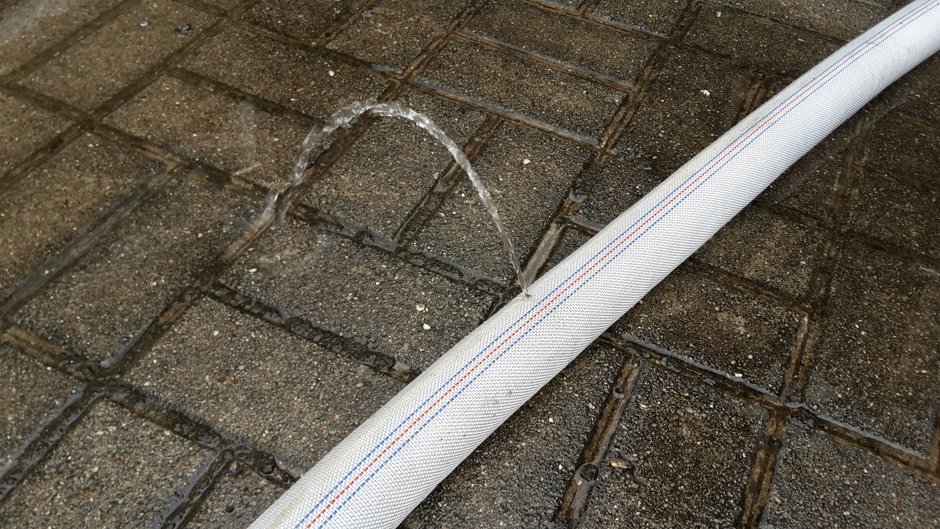
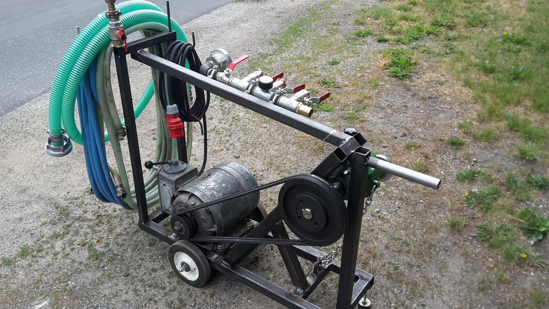
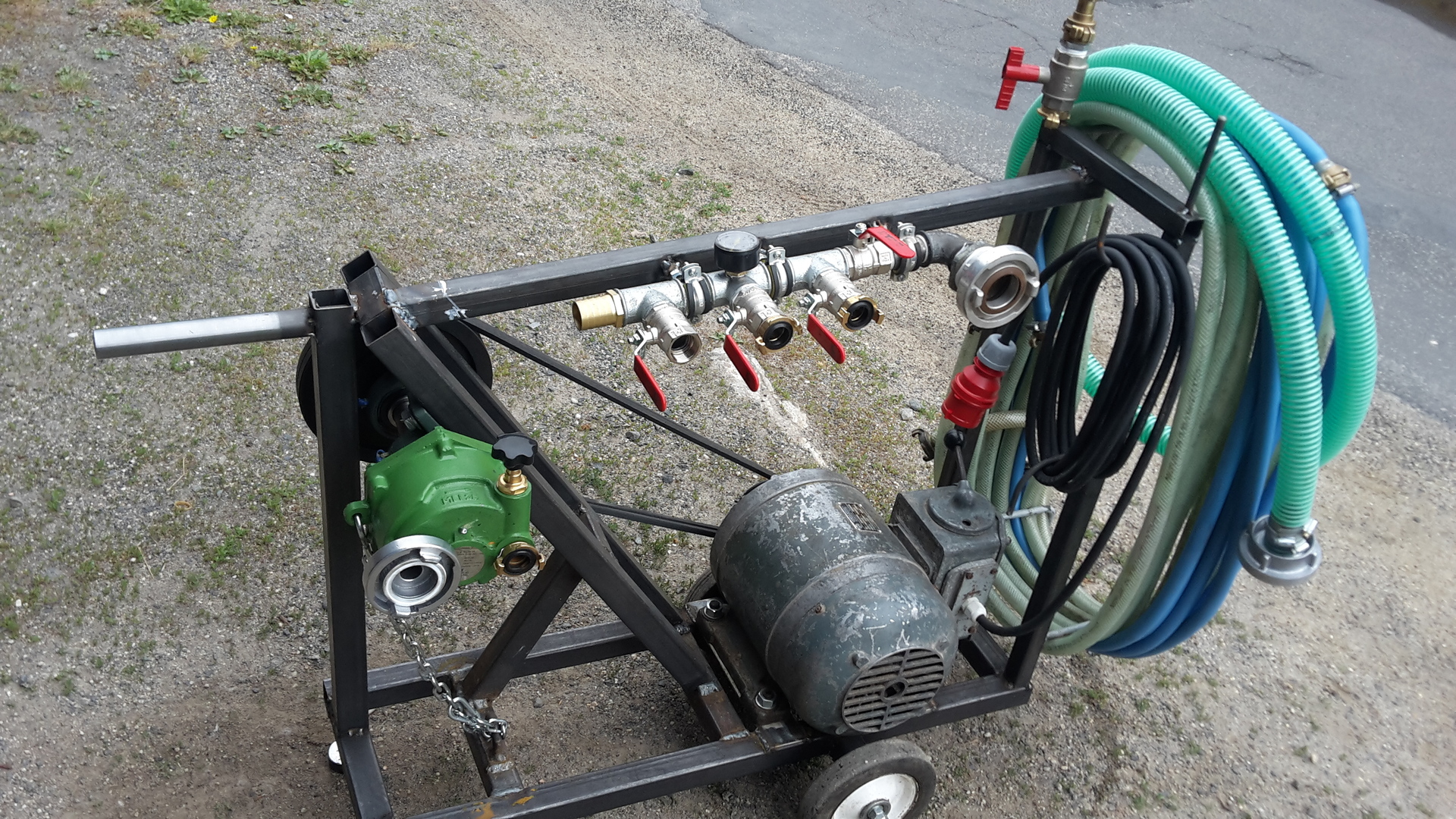
 High flow, medium pressure application
Components
Mechanical
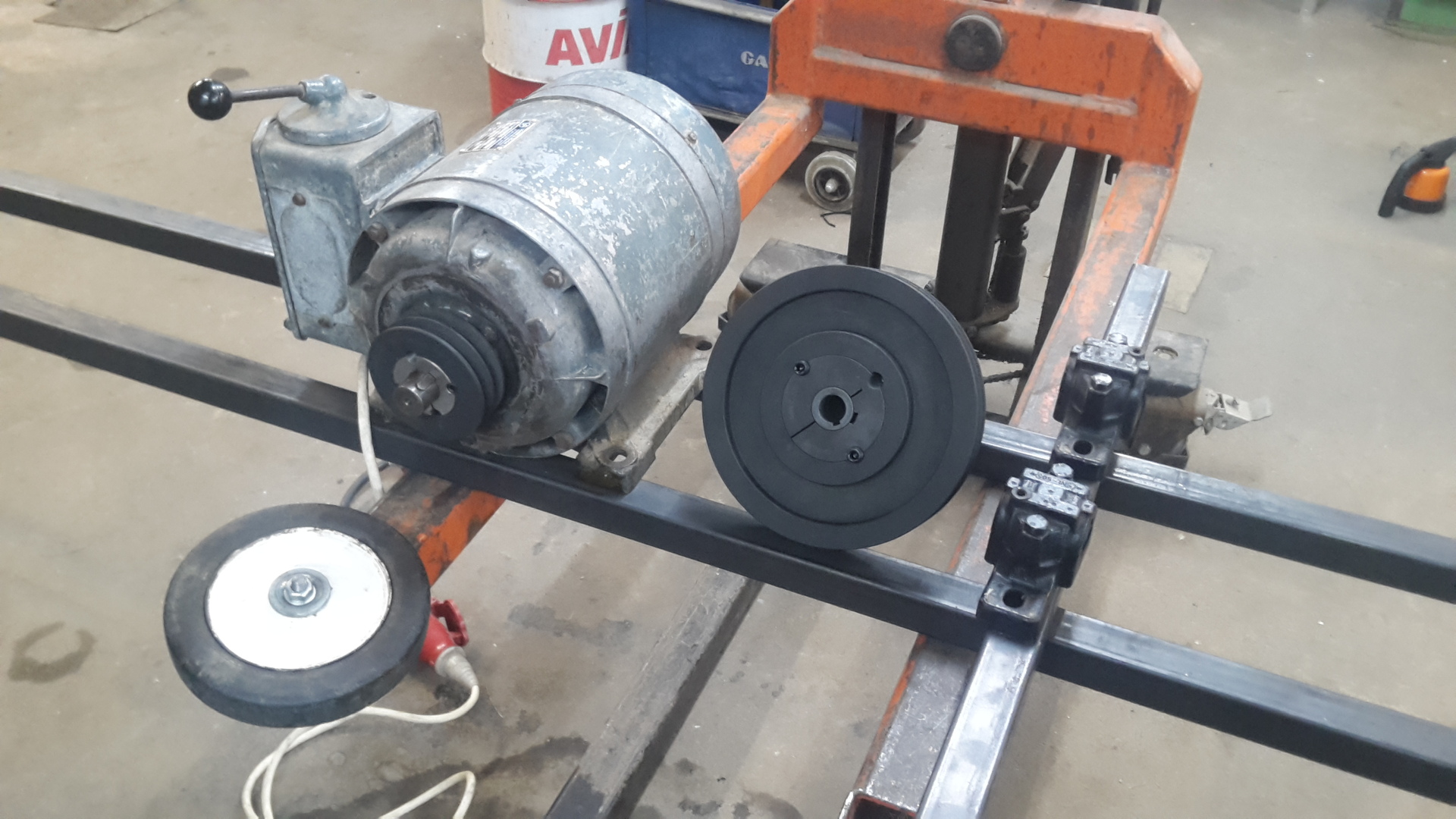
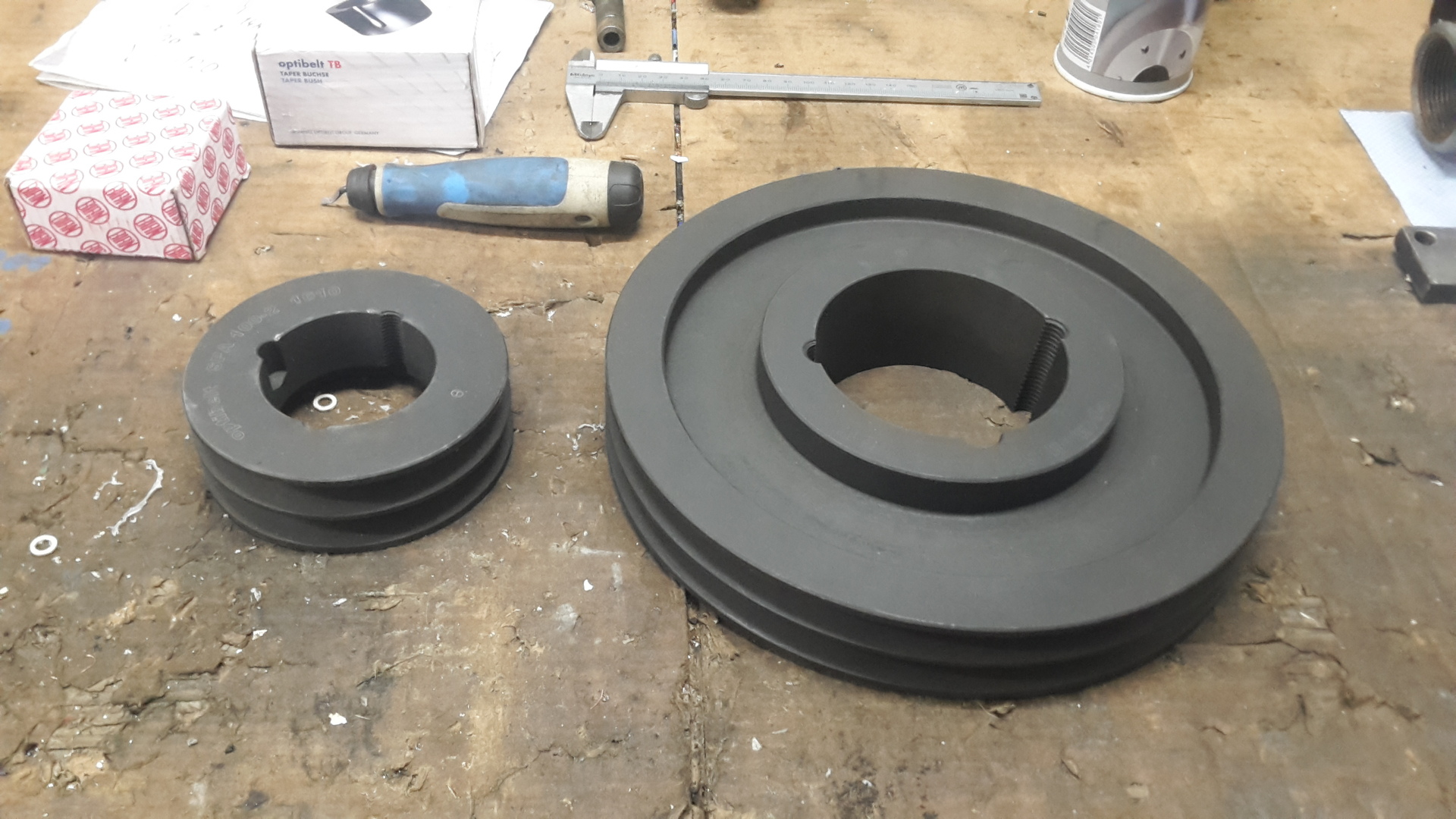
- Belt drive
- Pulley motor: 2x13mm, d=100mm
- Pulley PTO-shaft: 2x13mm, d=250mm
- 2 x 13mm v-belt
- Expansion tank: 8 Liter
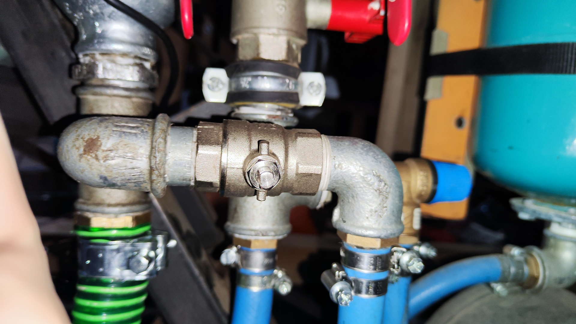
- Bypass valve: 3/4”
- Pressure relief valve: 10 bar
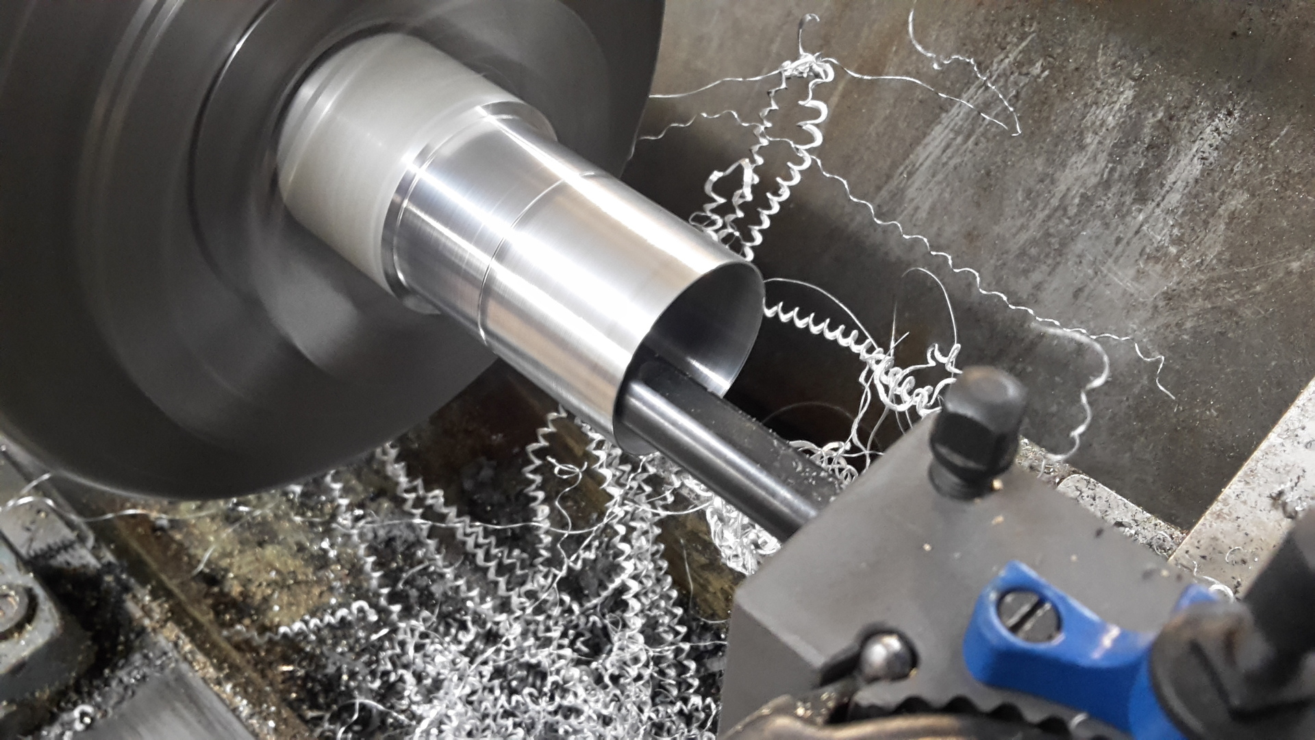
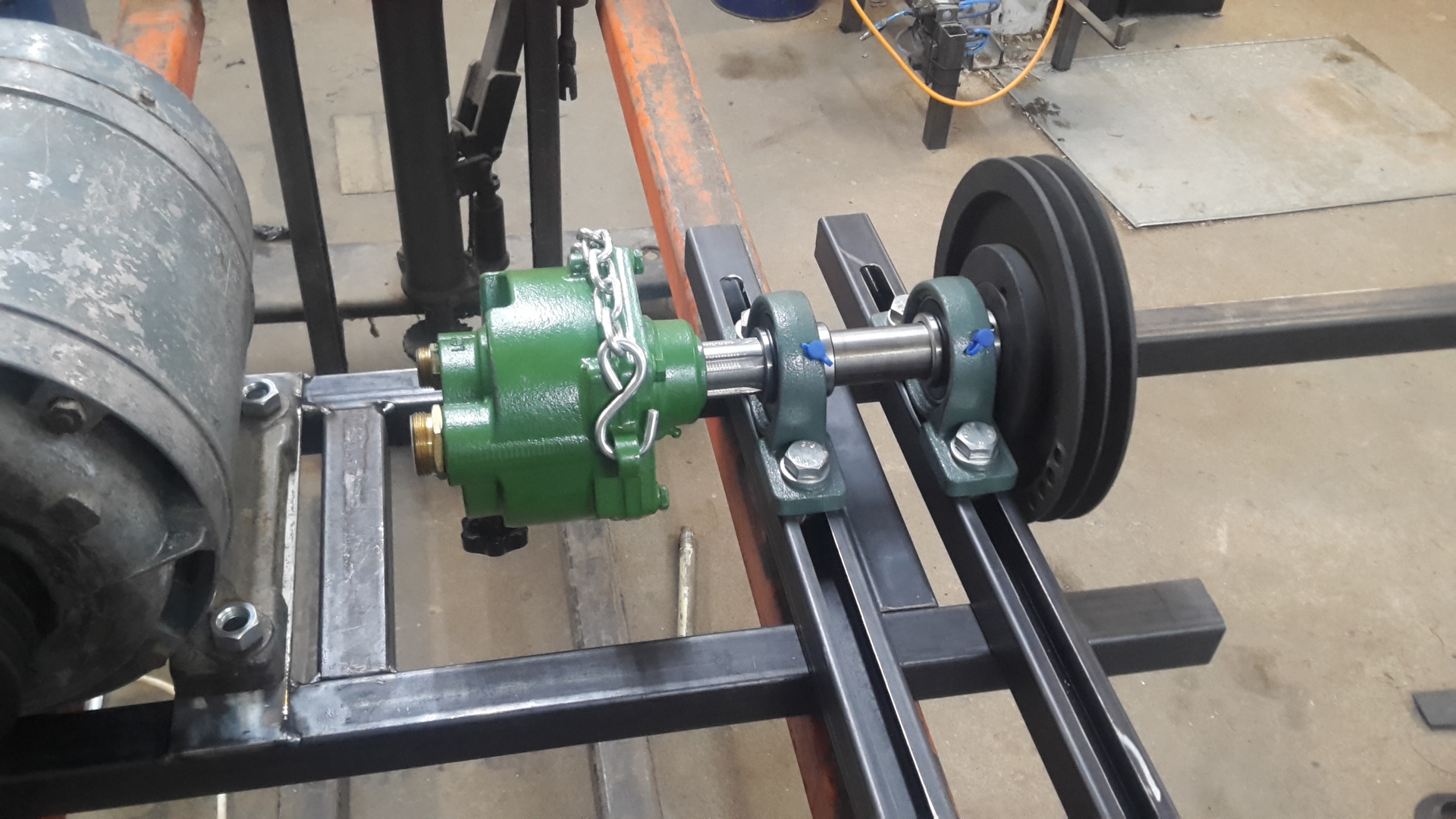
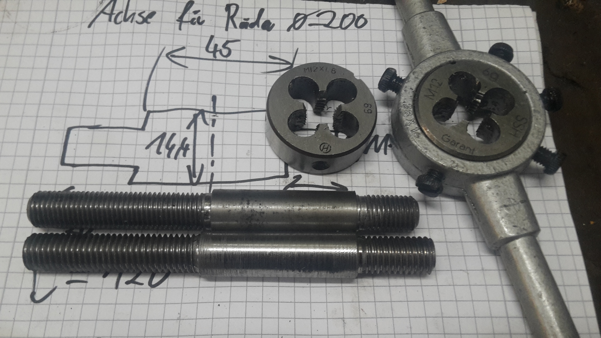
- PTO Shaft: 1 3/8” (34.9 mm)
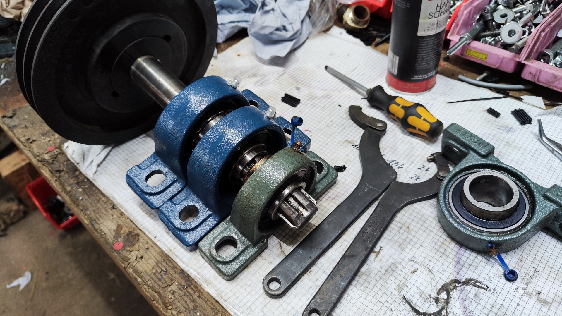
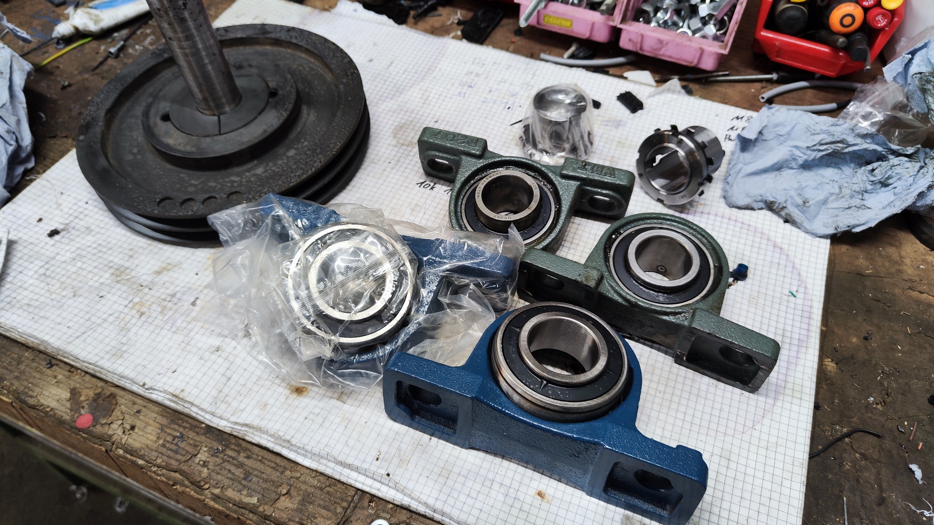
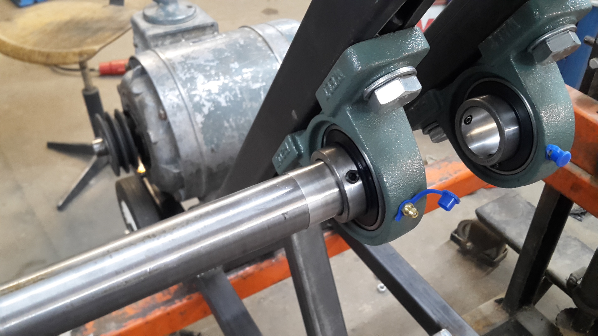
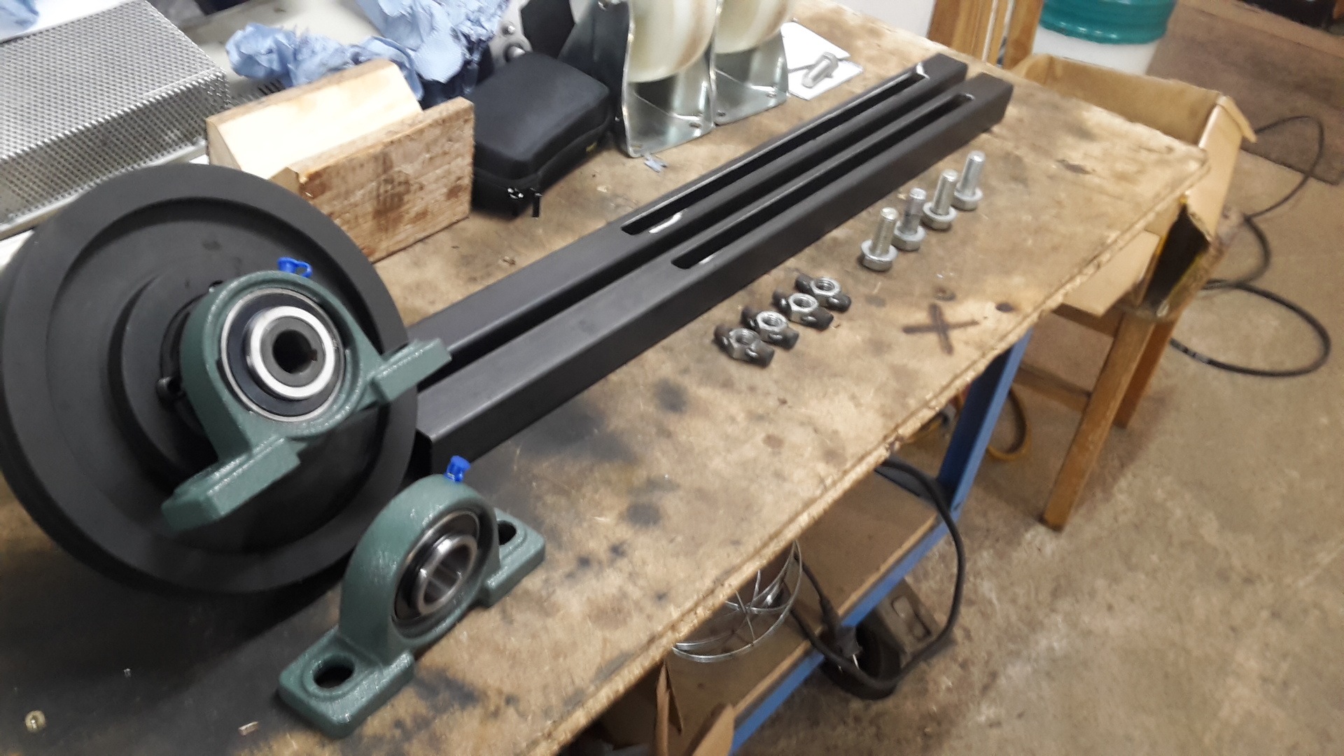
- Bearings: 2x 35 mm roller bearings with clamping sleeve
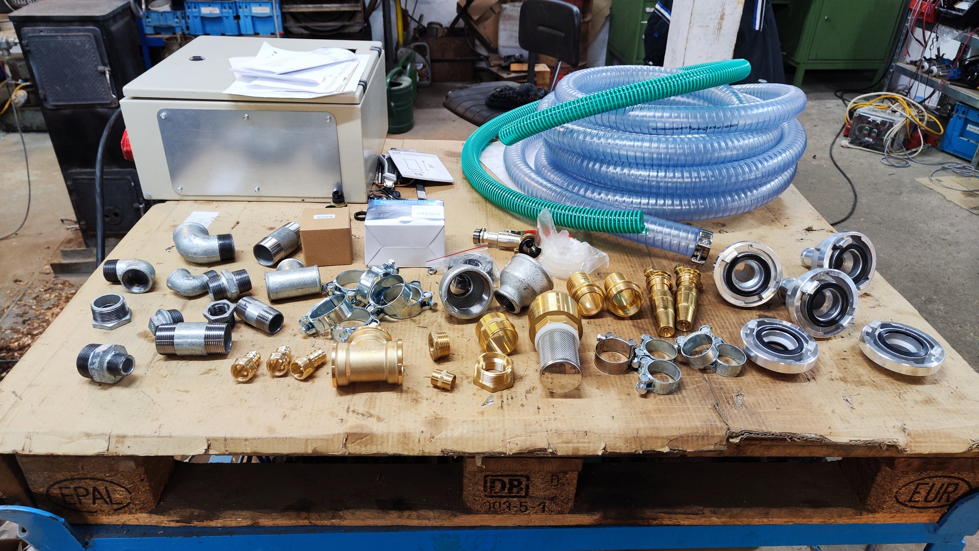
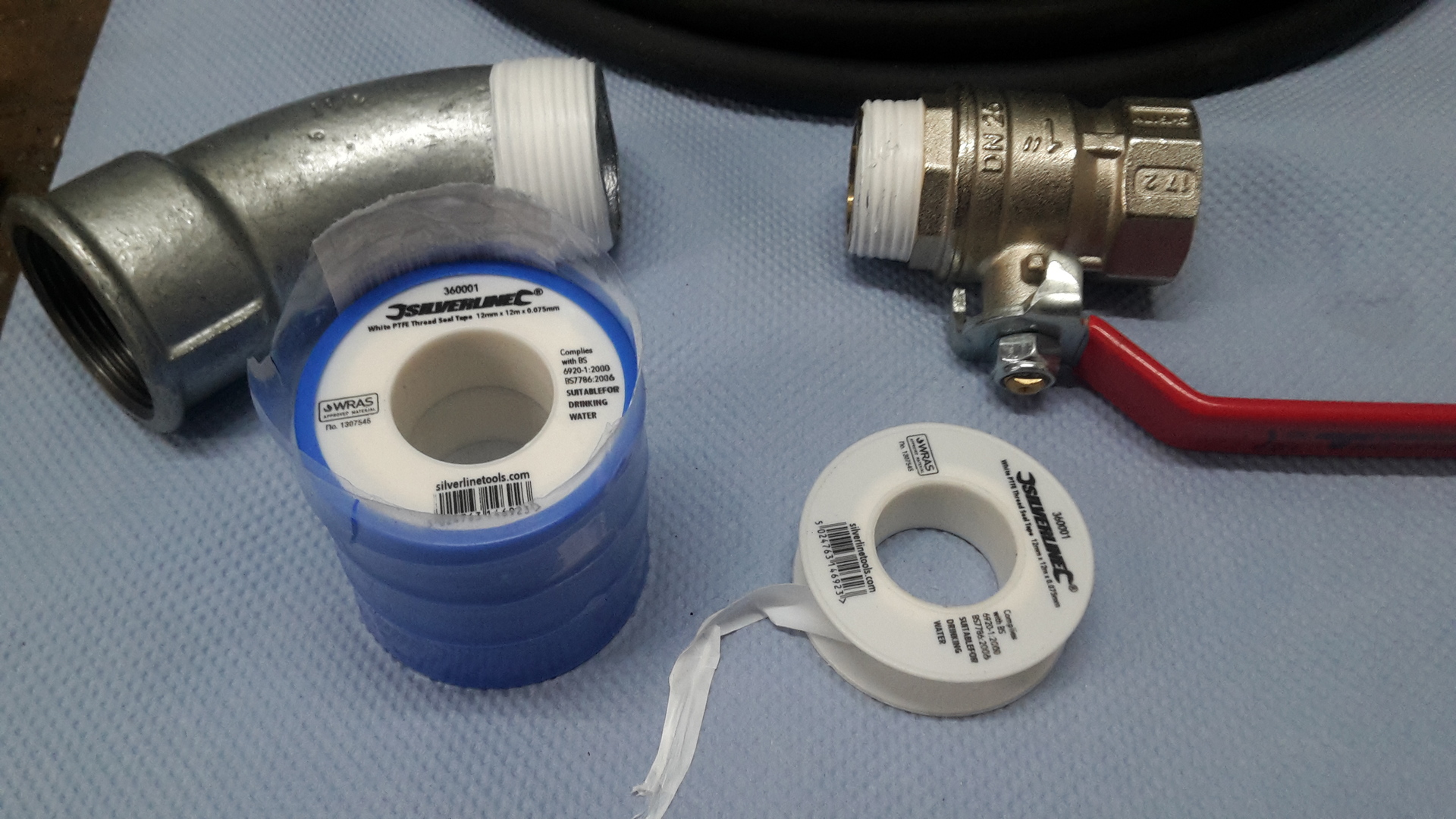
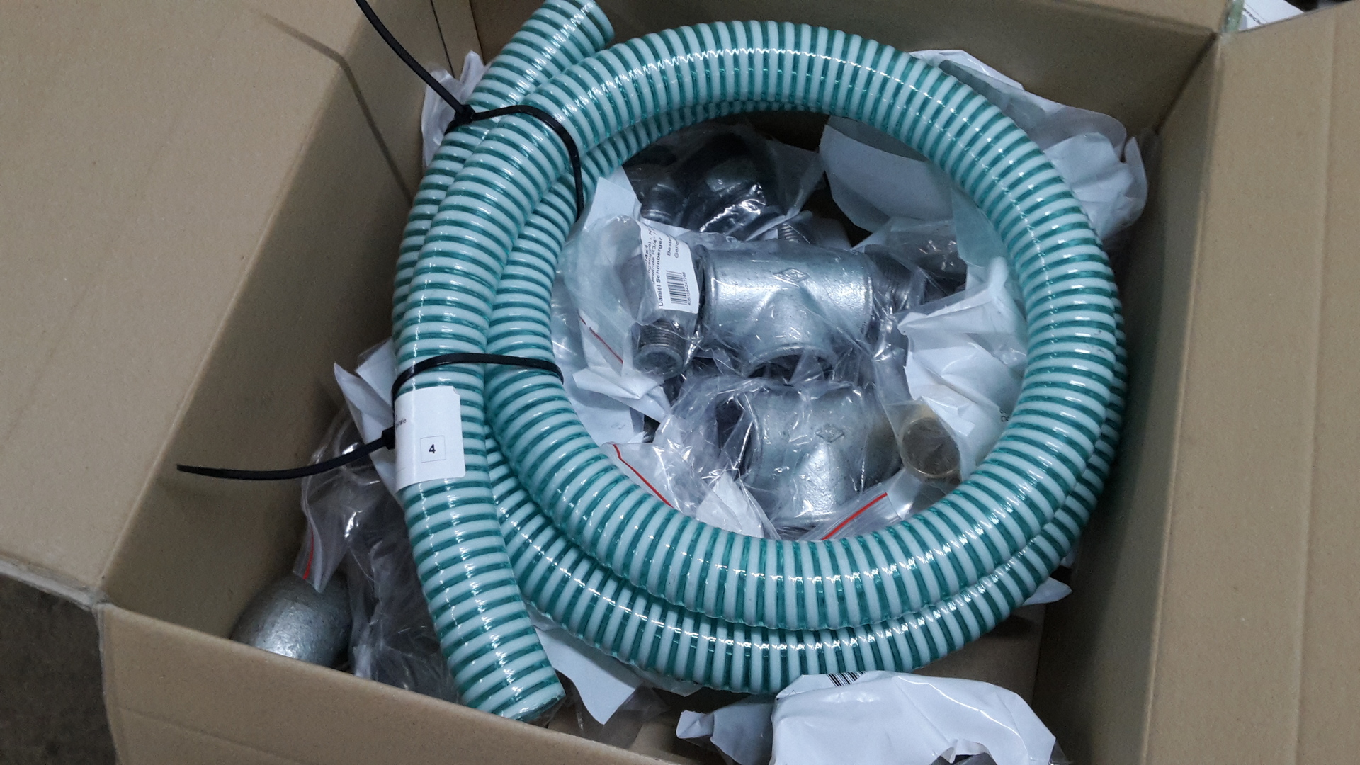
- Various fittings, valves, couplings…
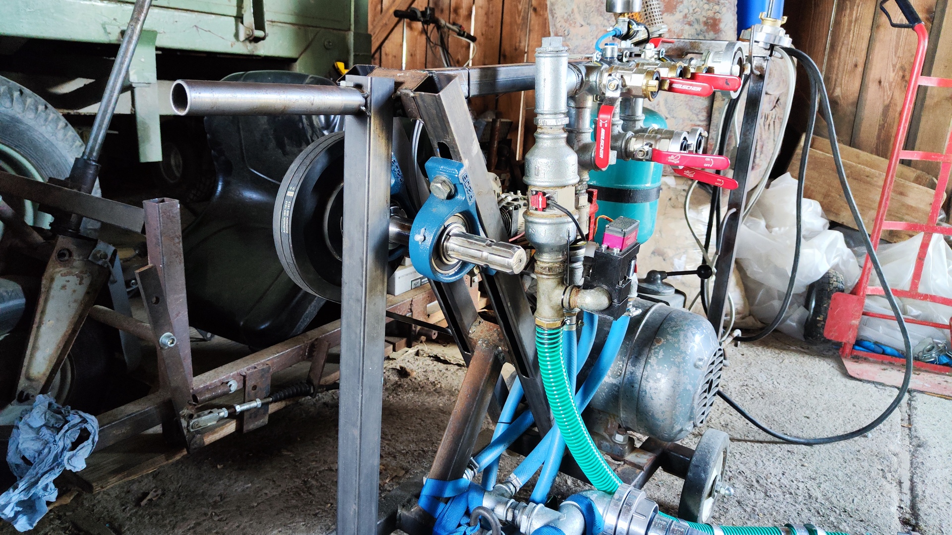
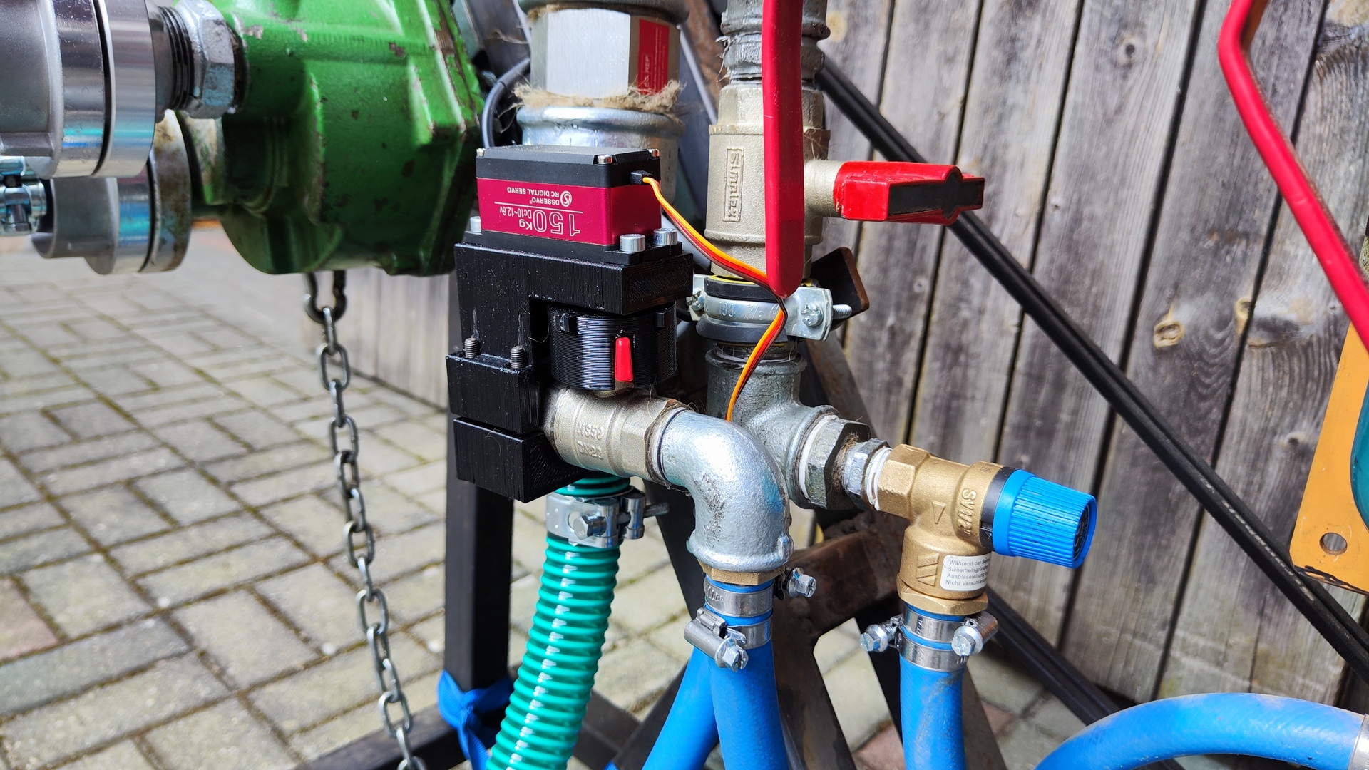
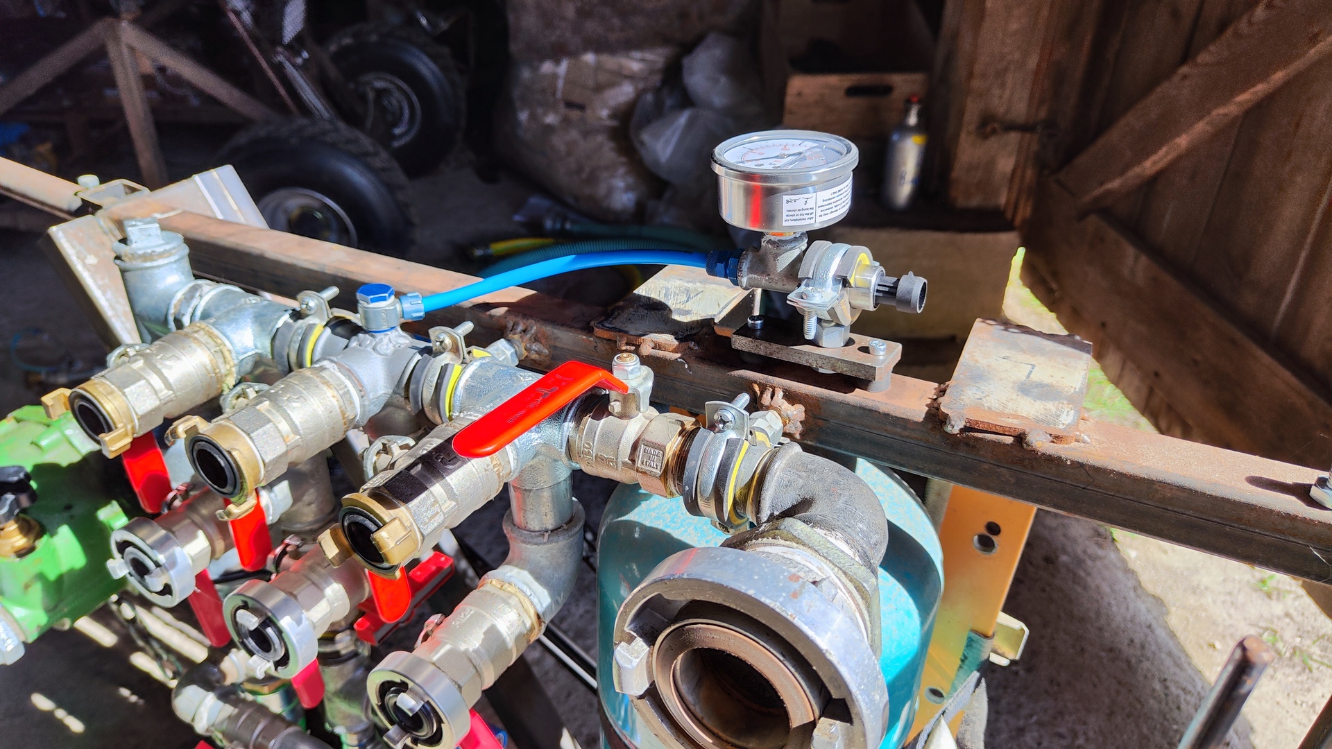
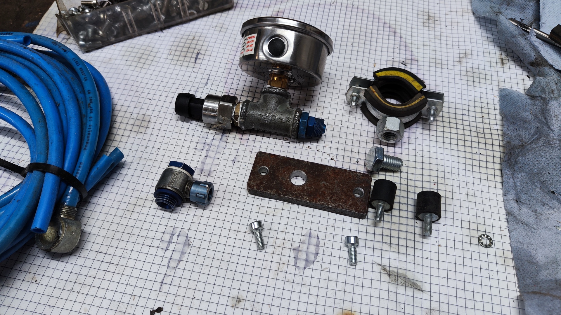
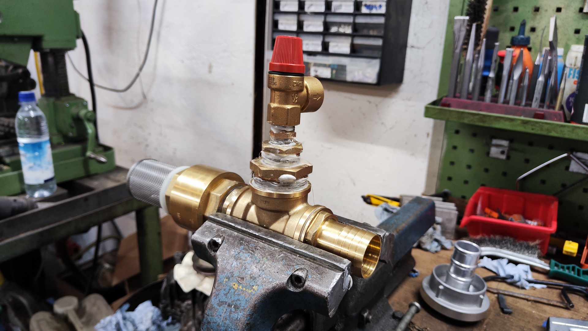
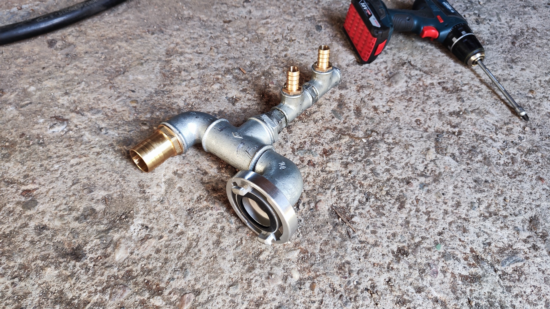
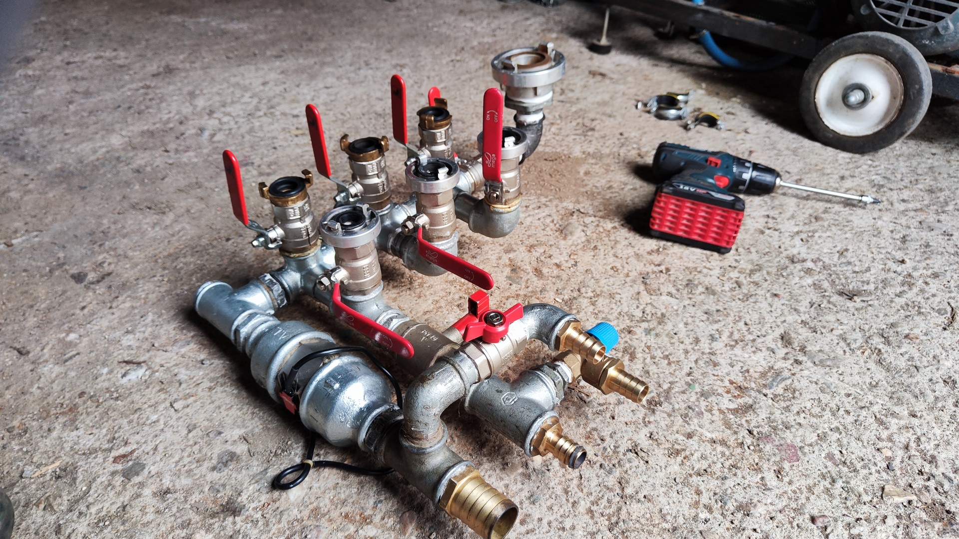
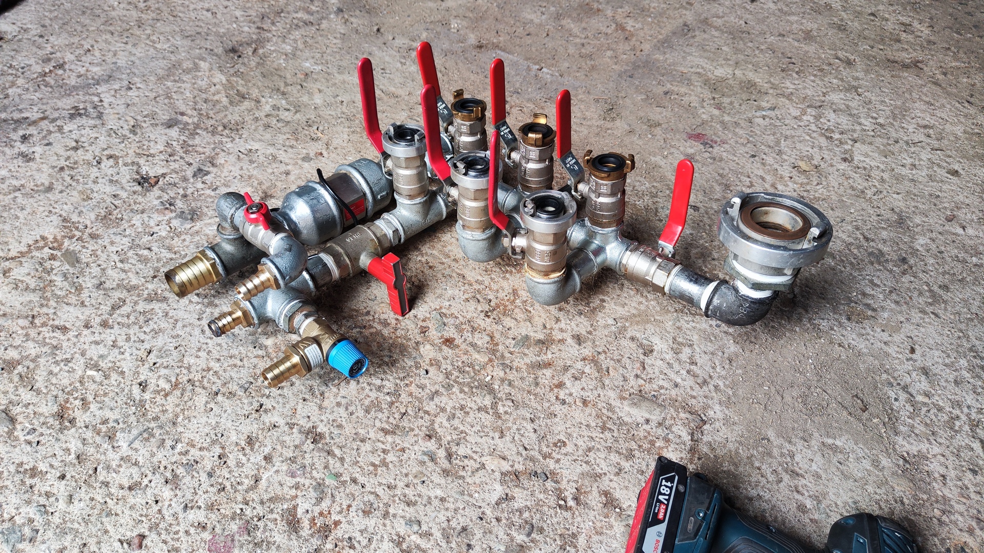
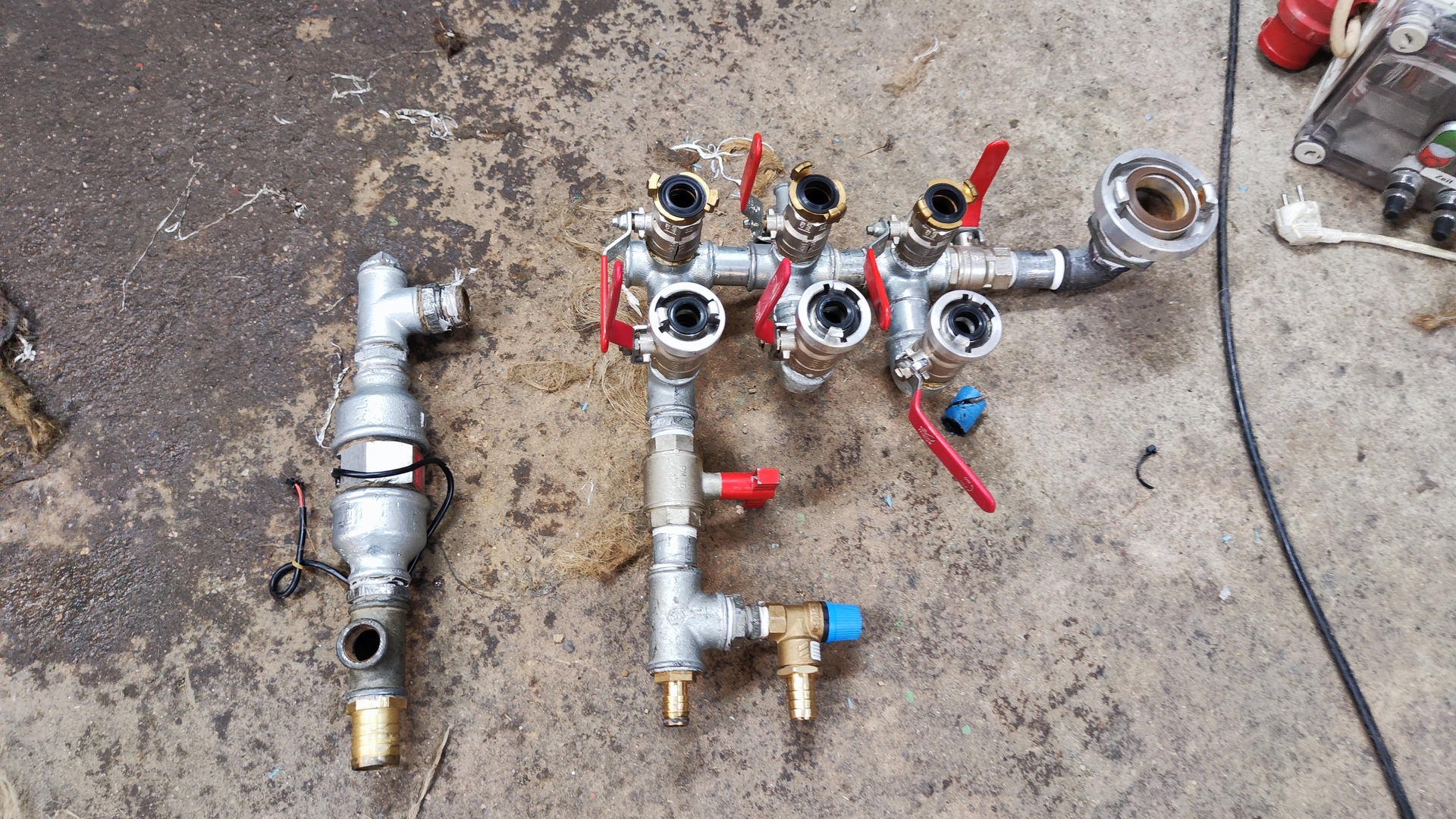
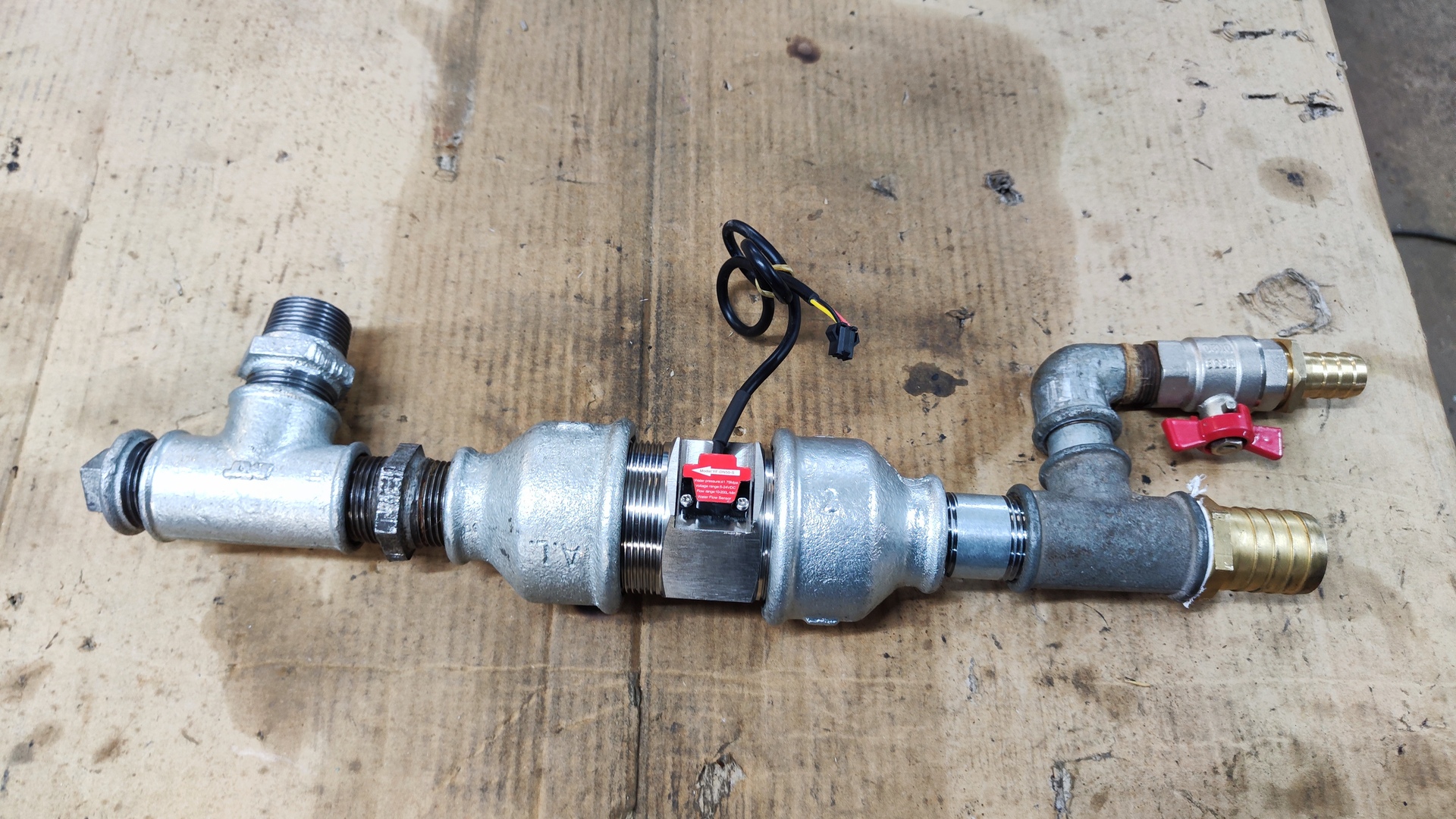
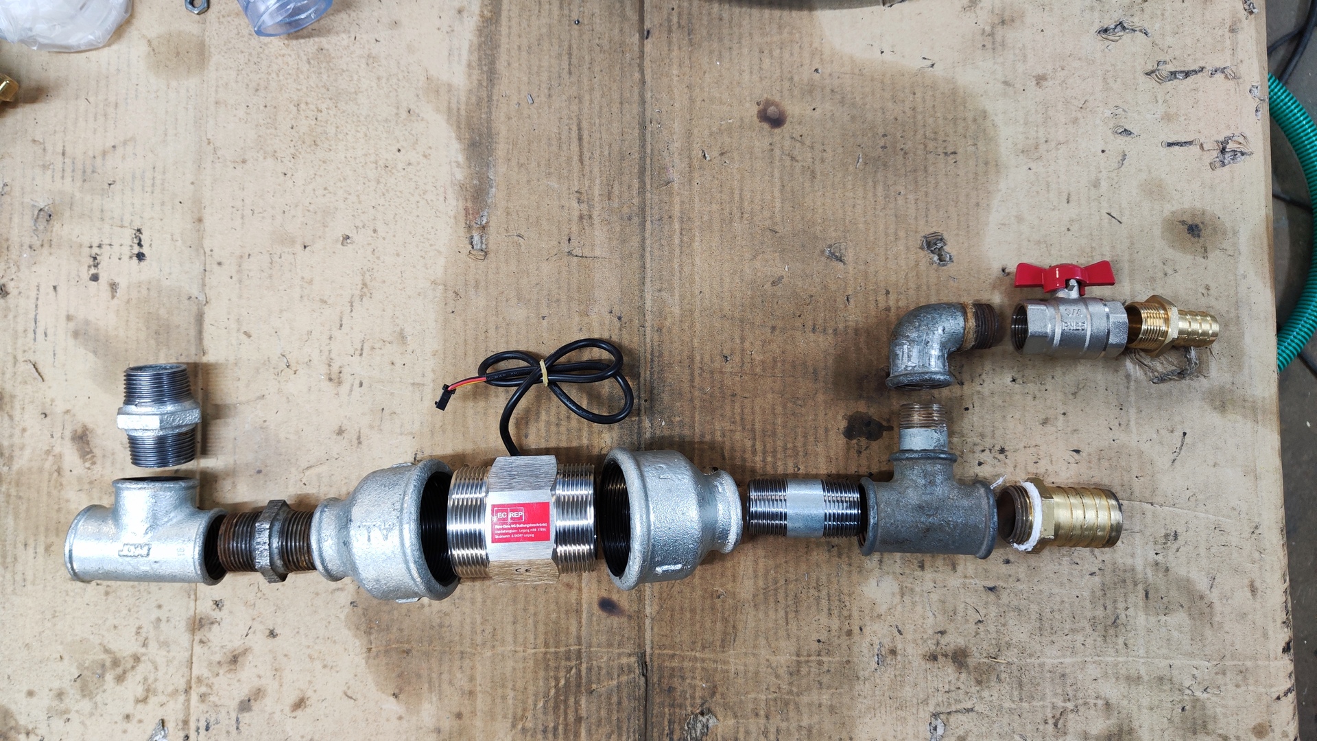
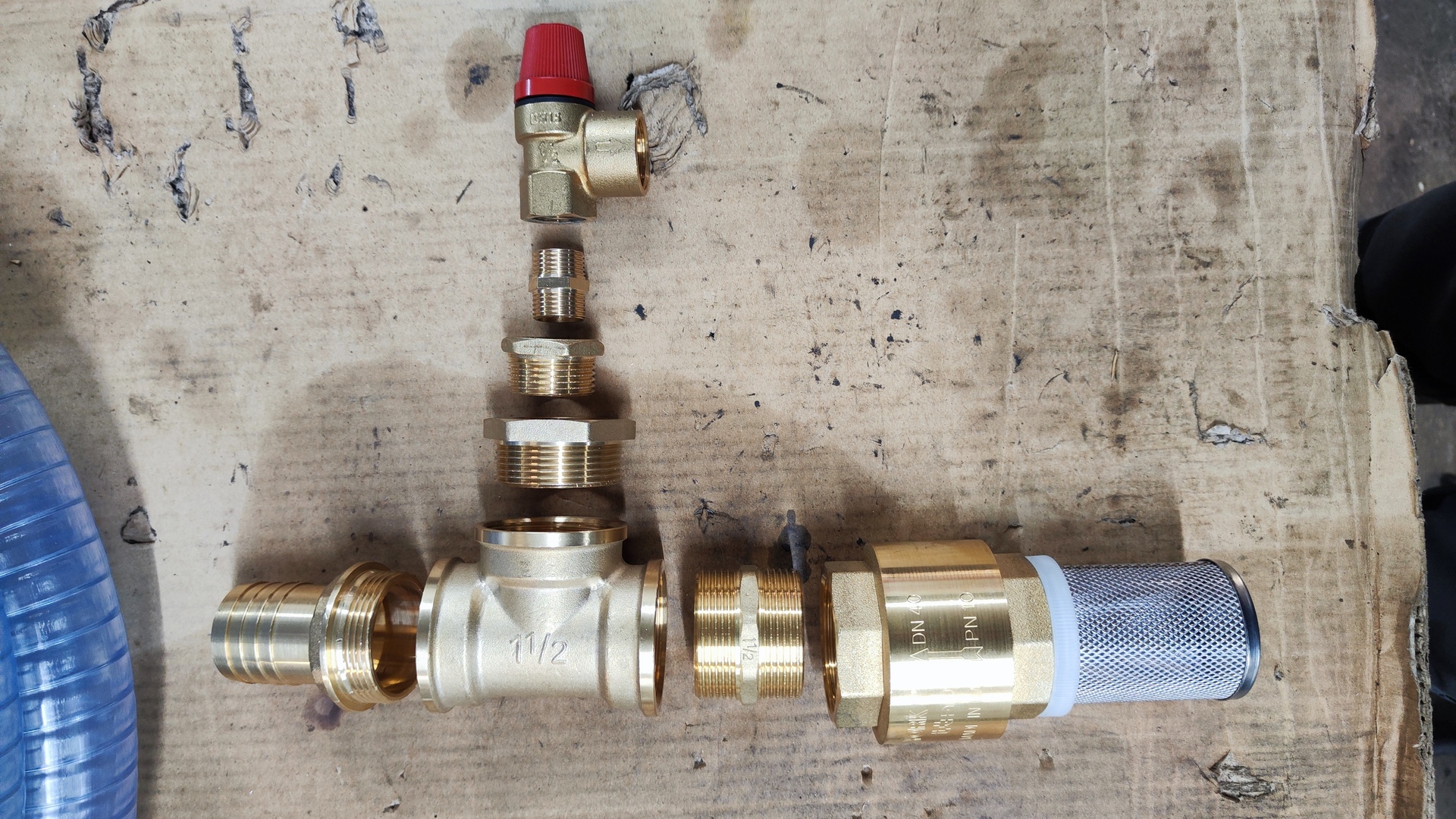
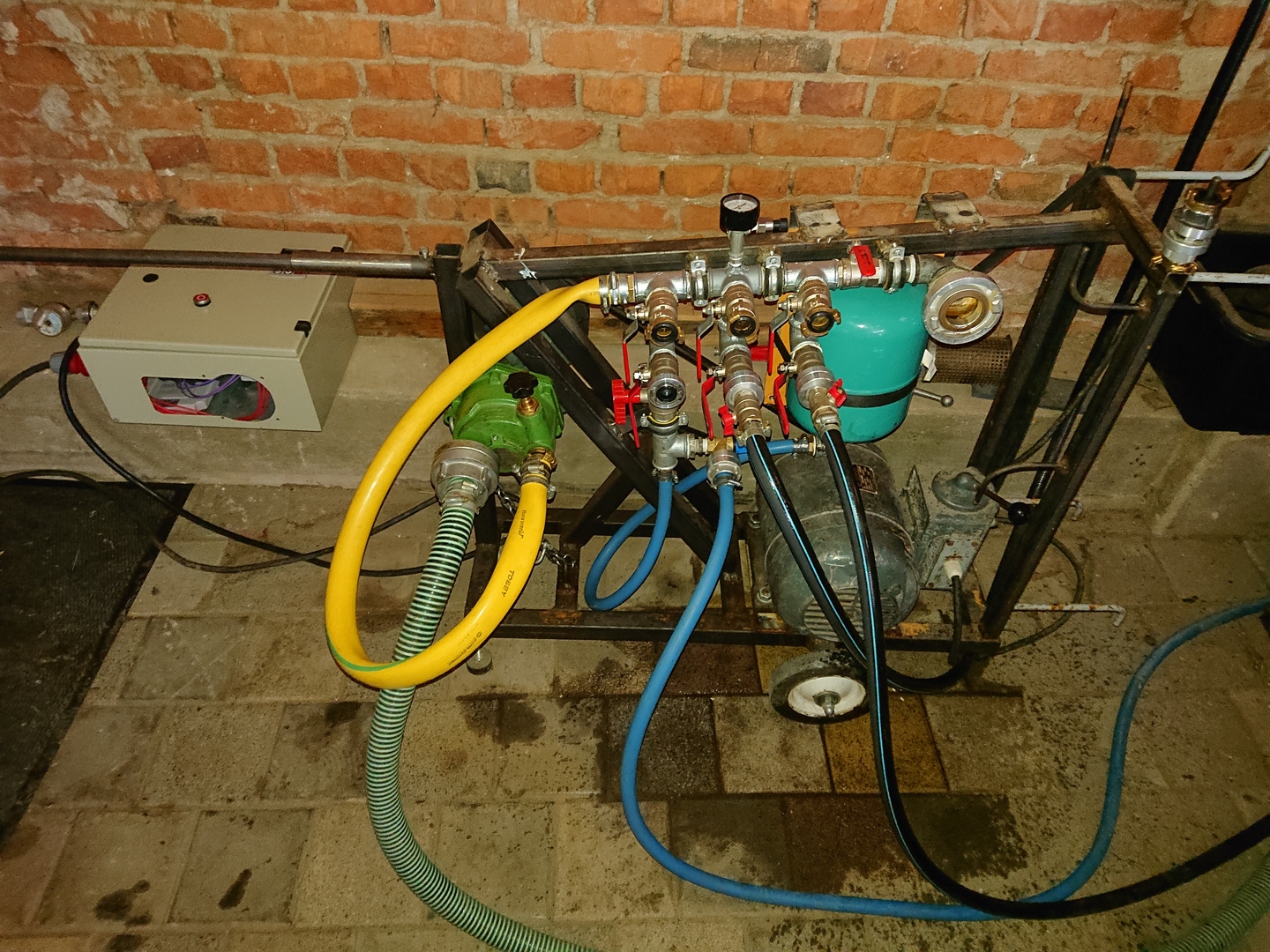
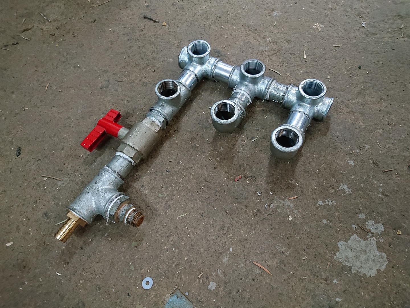
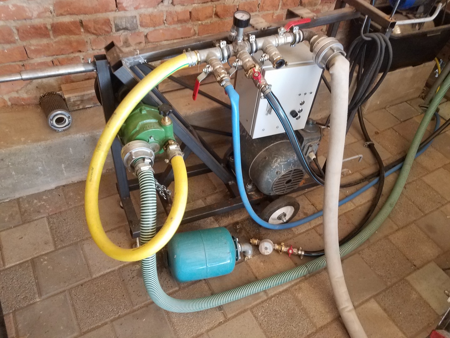
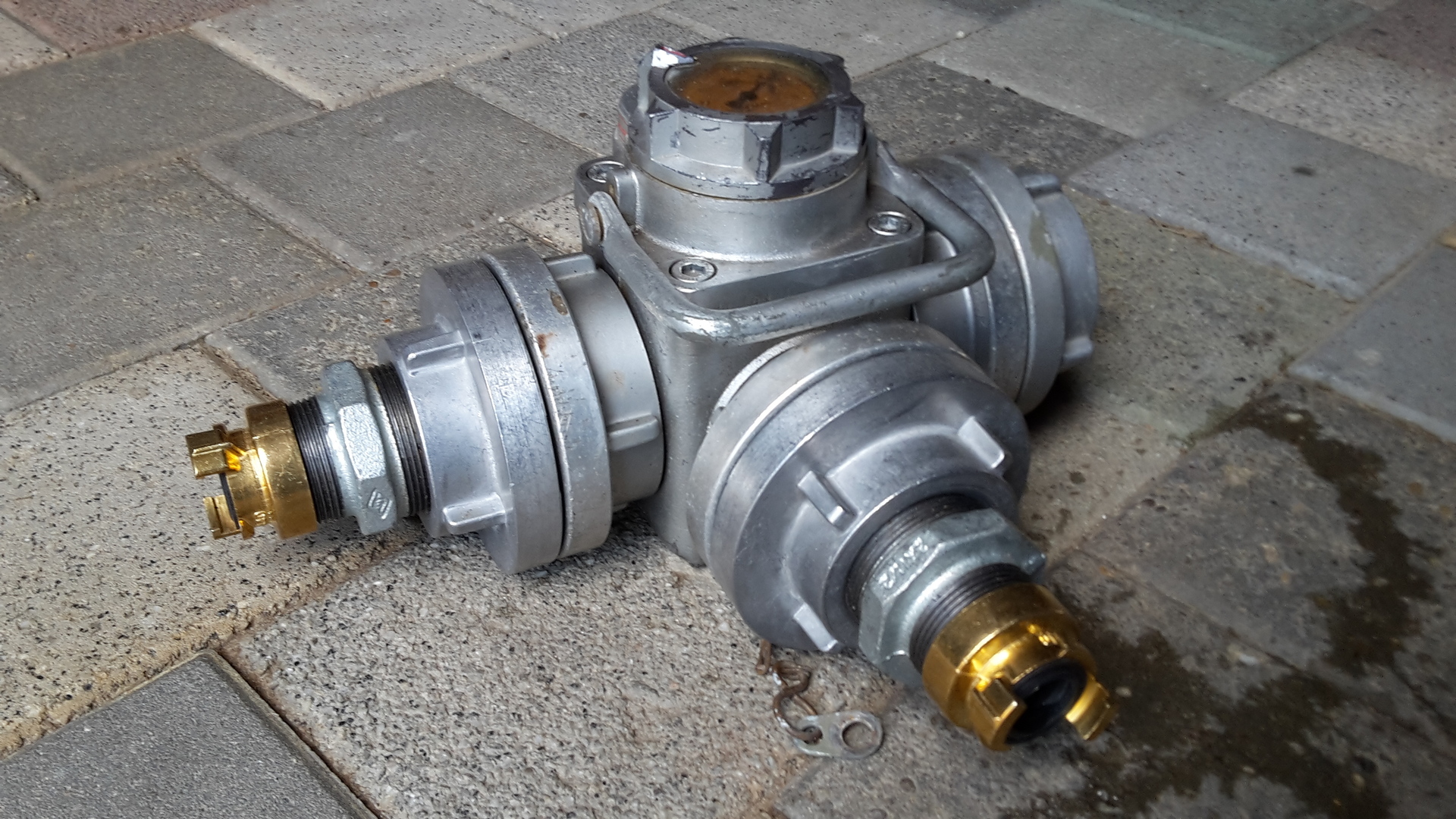
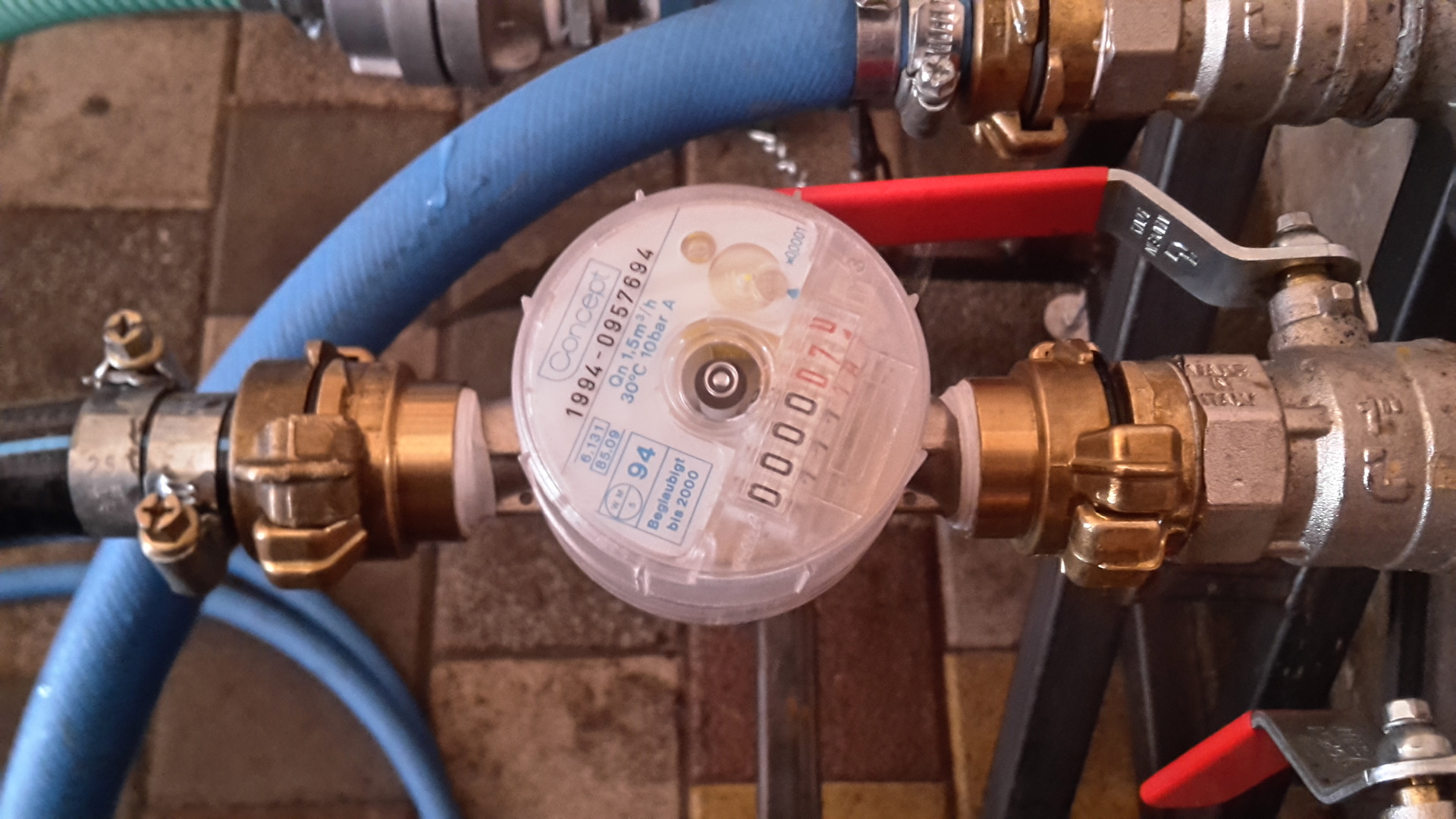
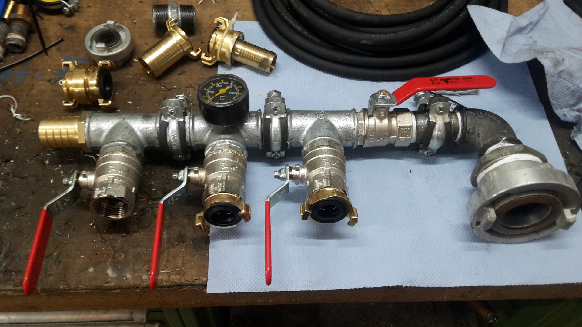
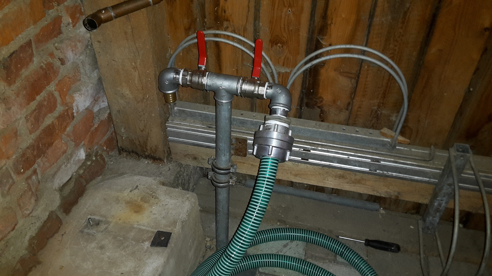
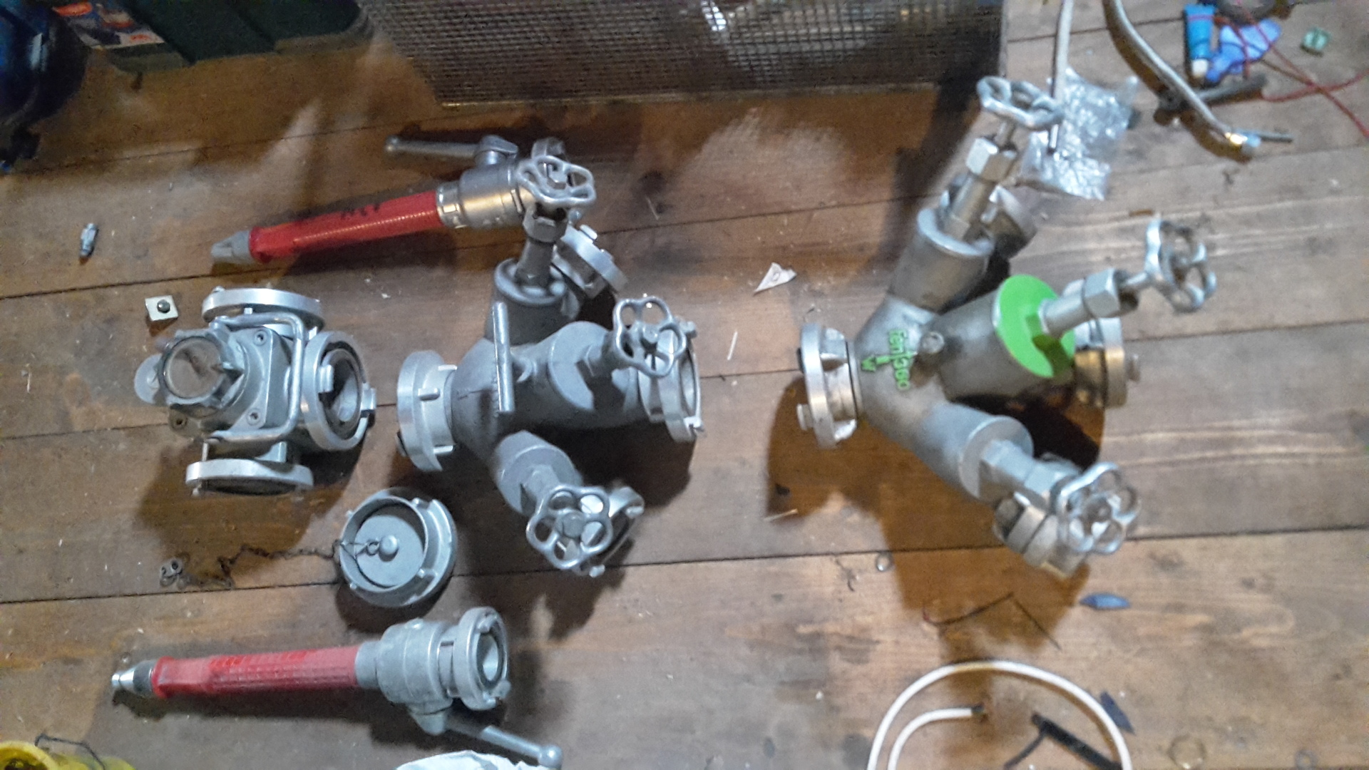
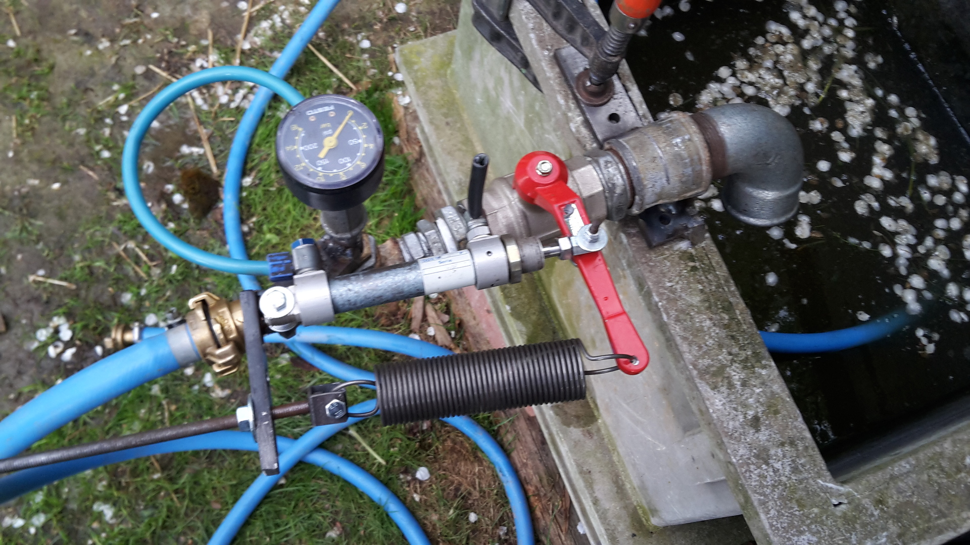
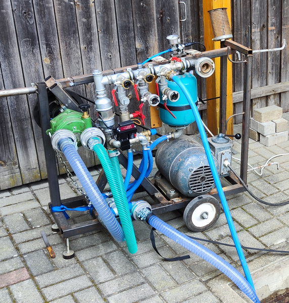
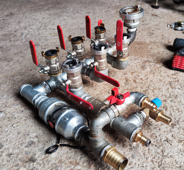 Main pipe assembly with flow sensor, bypass and pressure relief valve
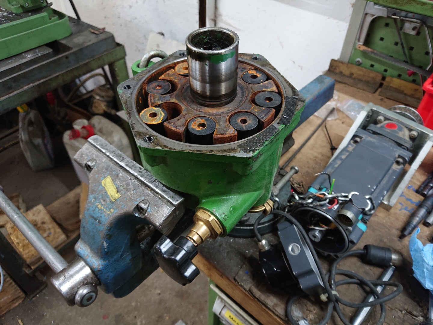
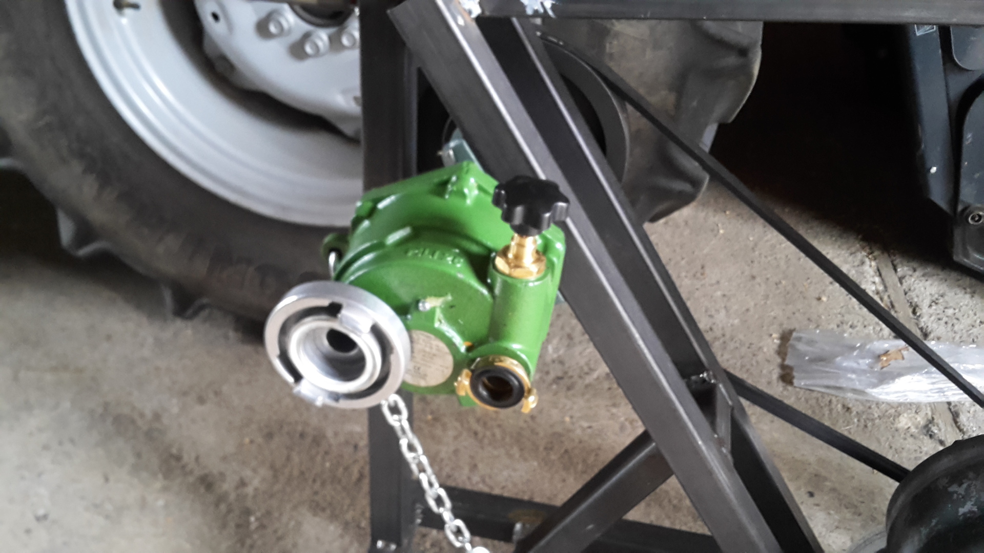
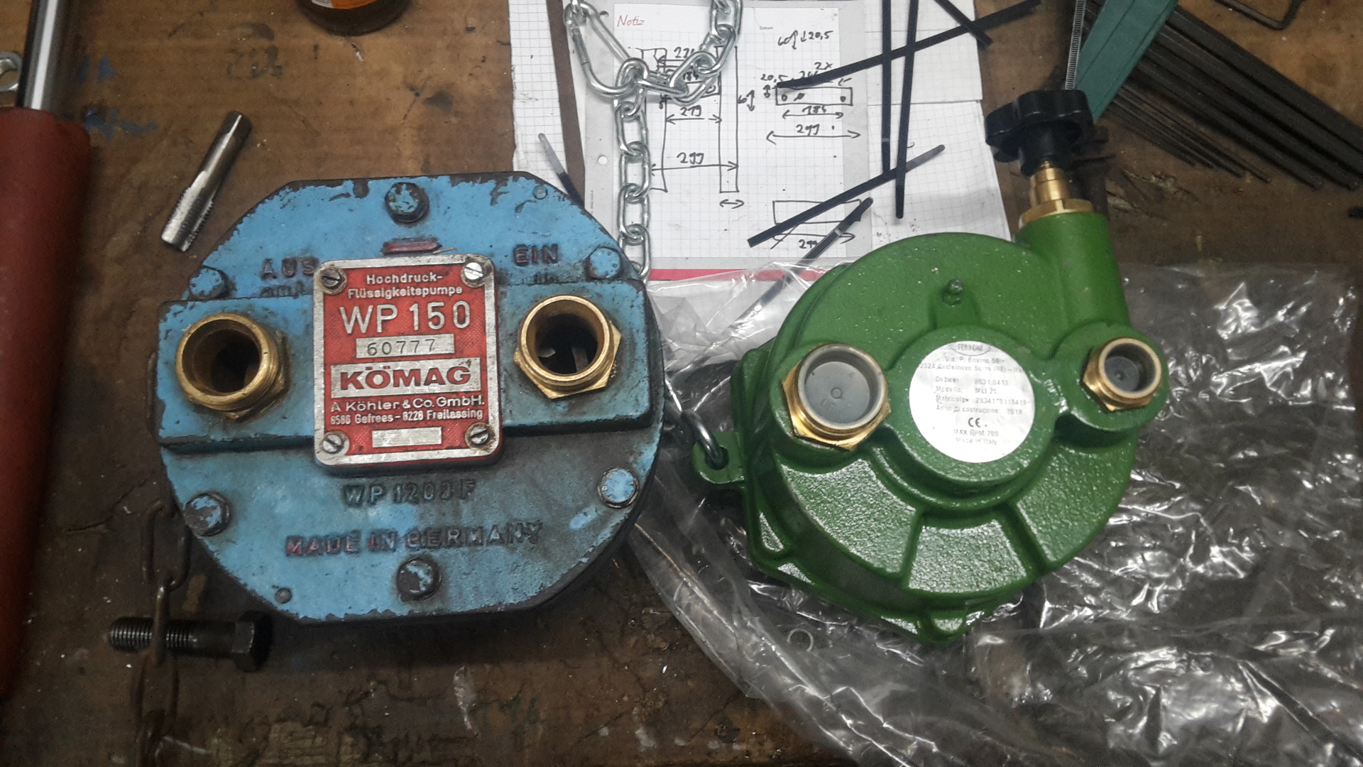
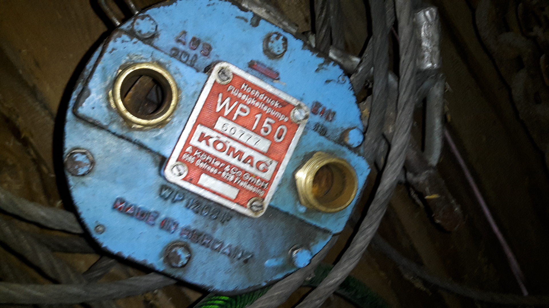
Pump
- Name: ML 20
- Power: 4 kW
- Rotational speed:
- Max: 700 rpm
- Rated: 540 rpm
- Connection: 1 3/8”, 6 Tooth PTO shaft
- Max. Pressure: 25 bar
- Flow rate:
- Low pressure: 180 l/min
- High pressure: 70 l/min
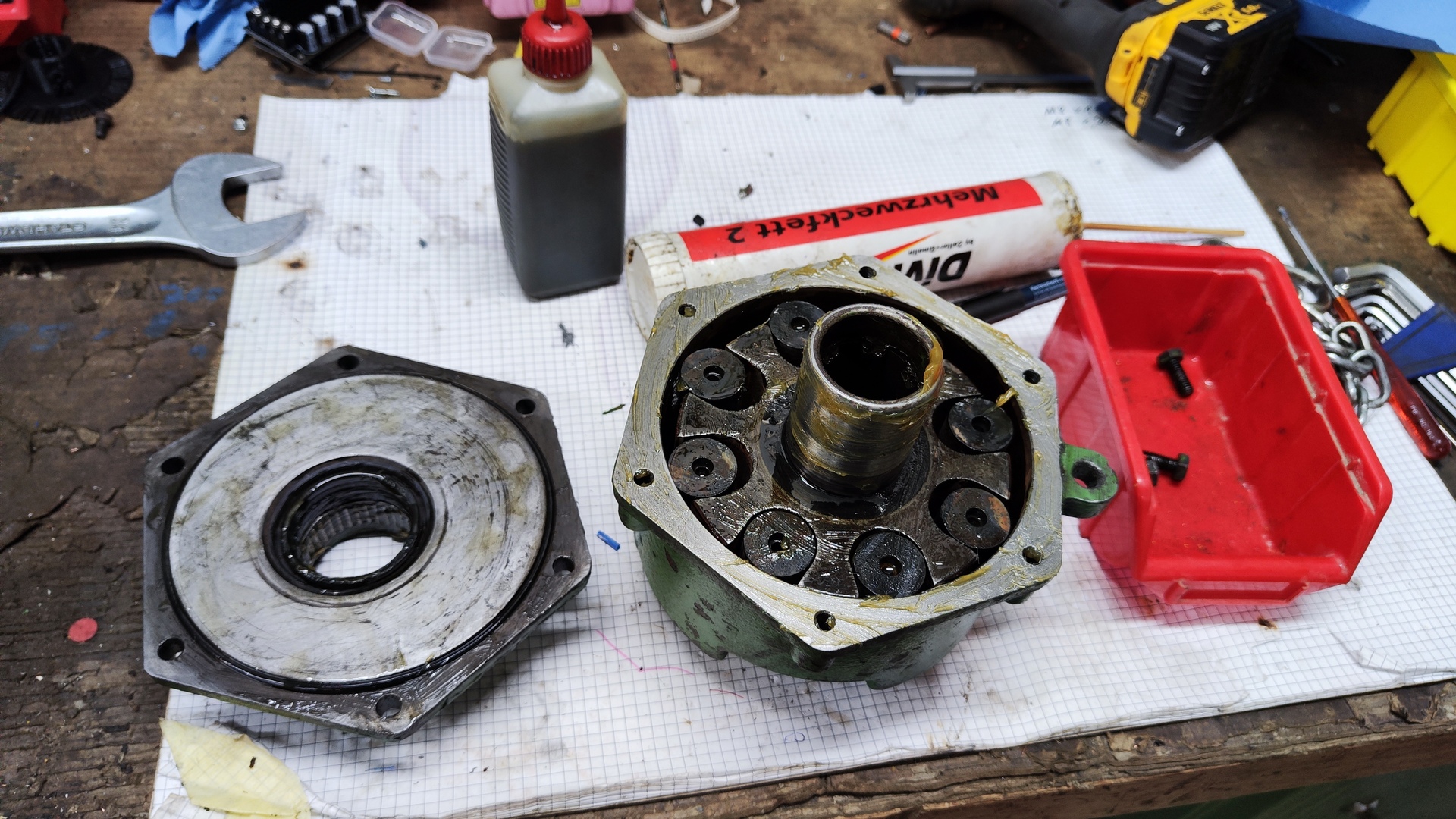
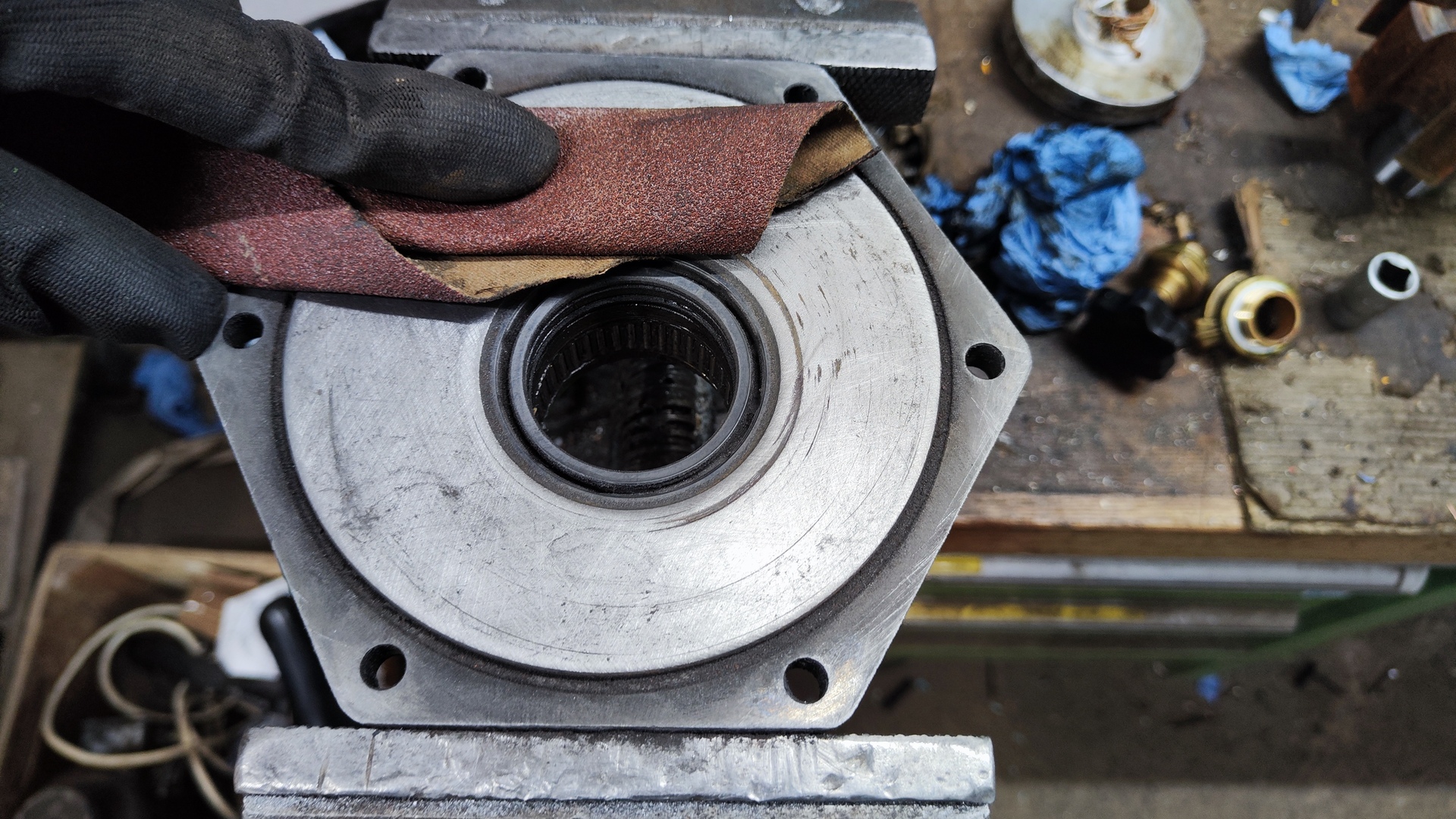
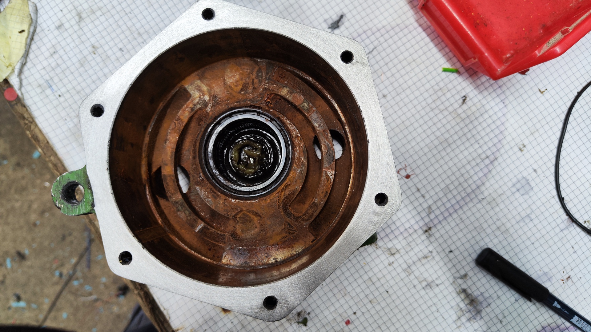
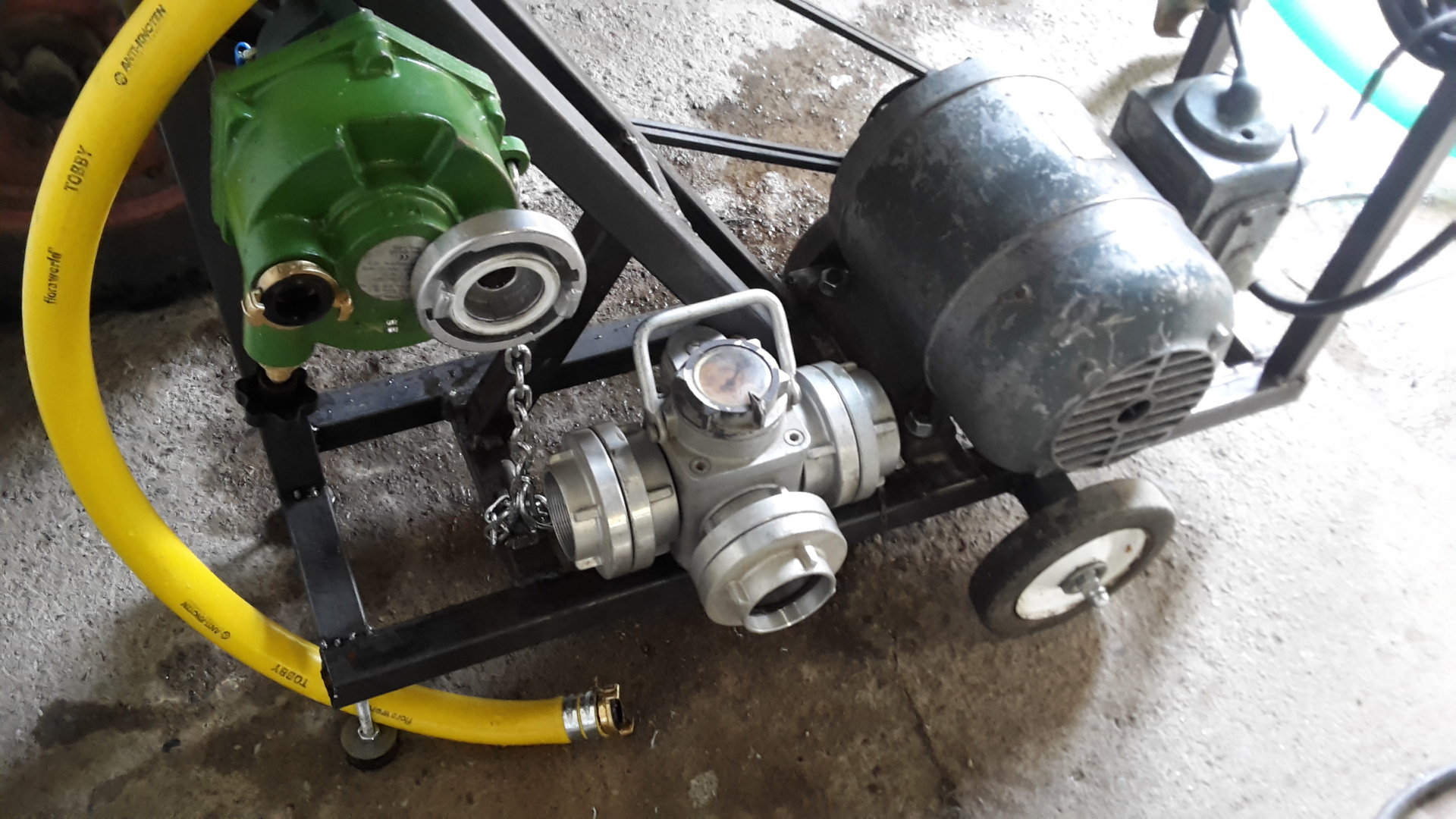
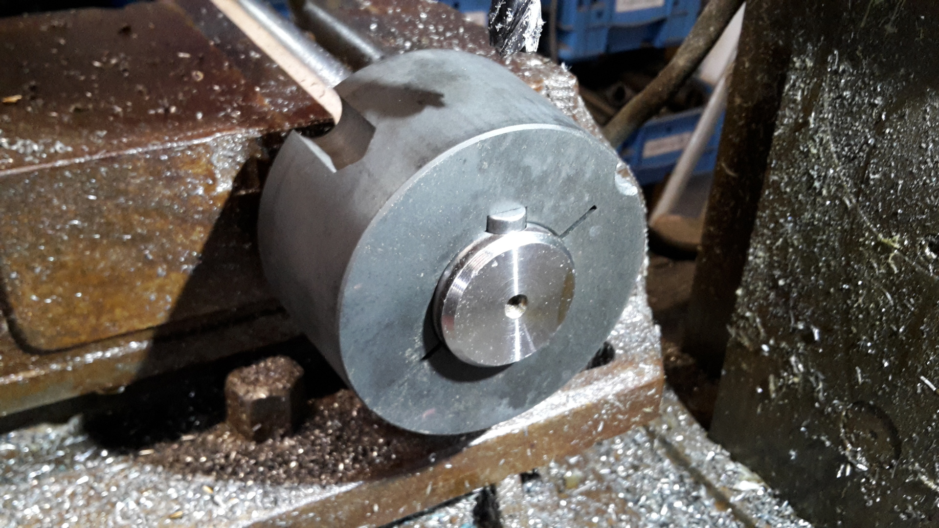
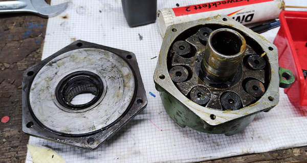 PTO-Pump with cover removed
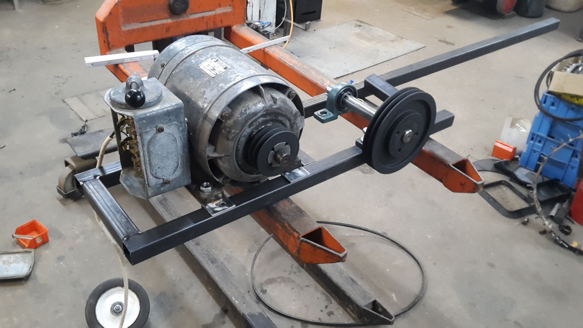
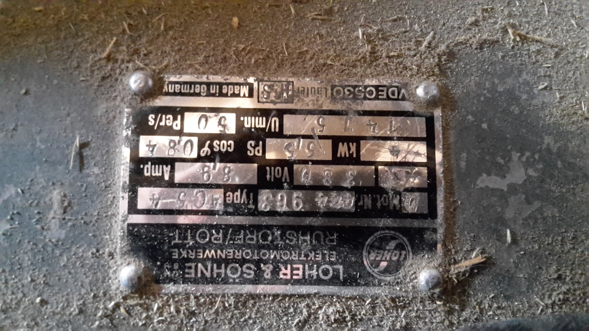
Motor
- Rated power: 4 kW
- Rotation speed: 1415 rpm
- Voltage: 380 V
- Frequency: 50 Hz
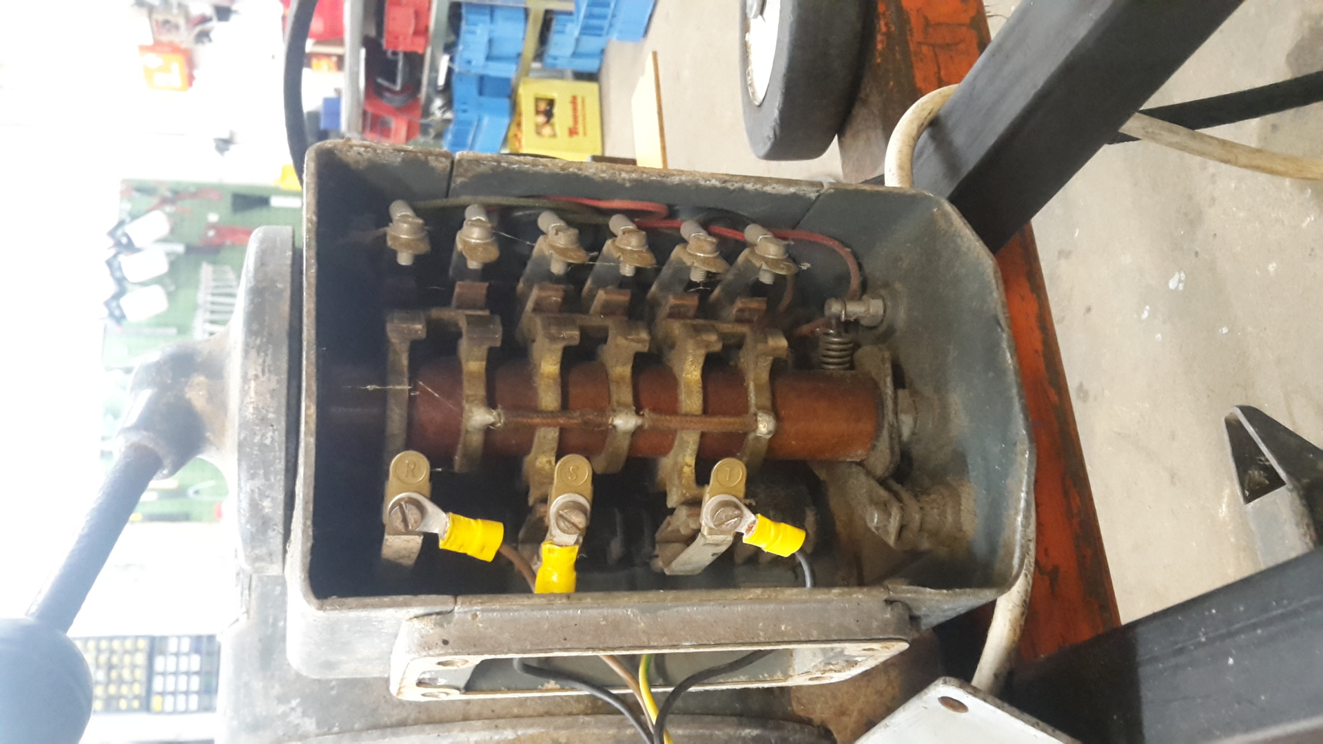
- Type: Three phase asynchronous motor
- Attachment: Star-delta cam switch
- Previous application: Powering a stationary thresher
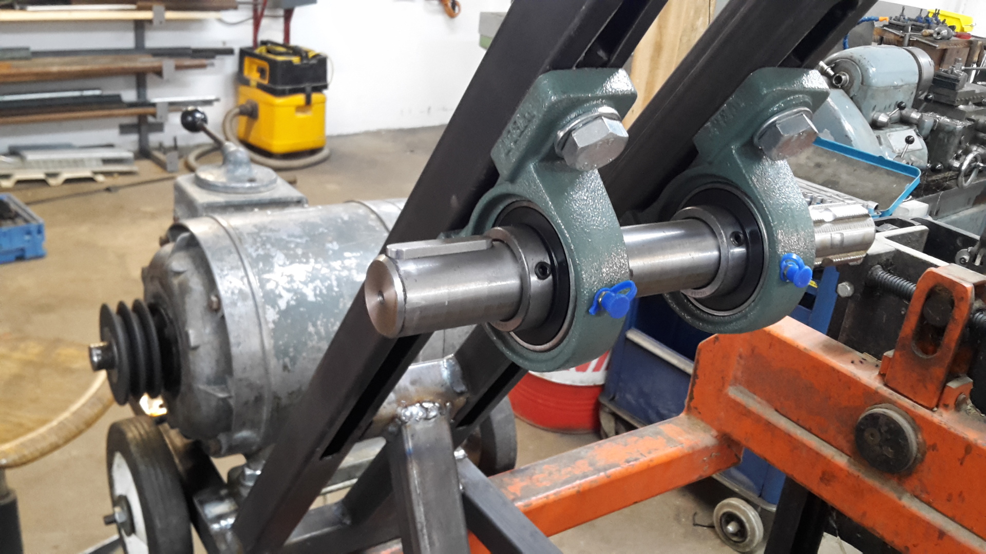
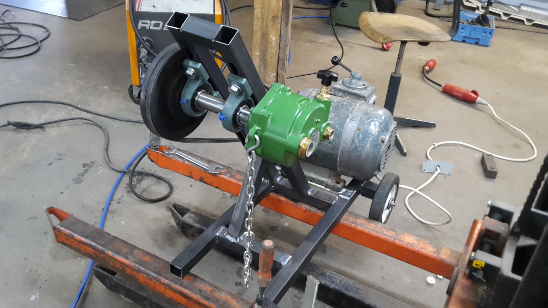
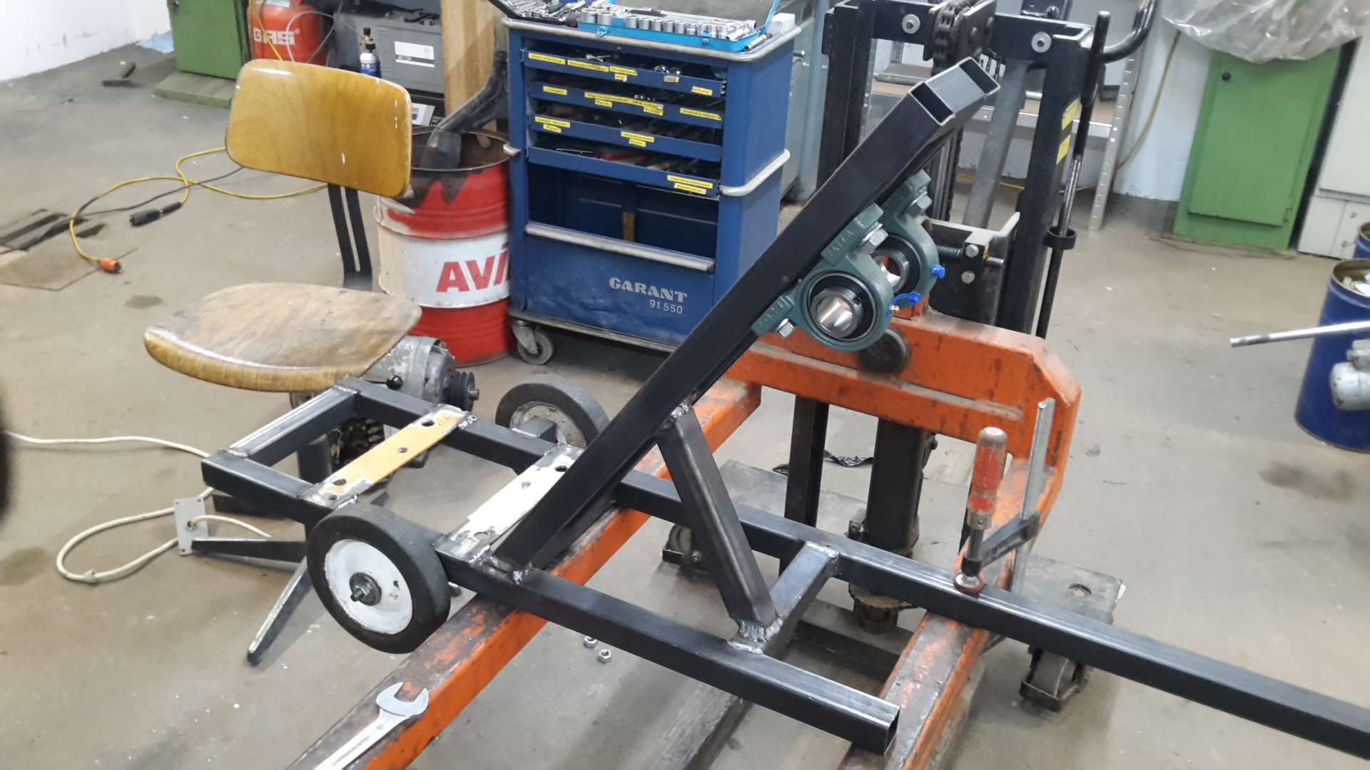
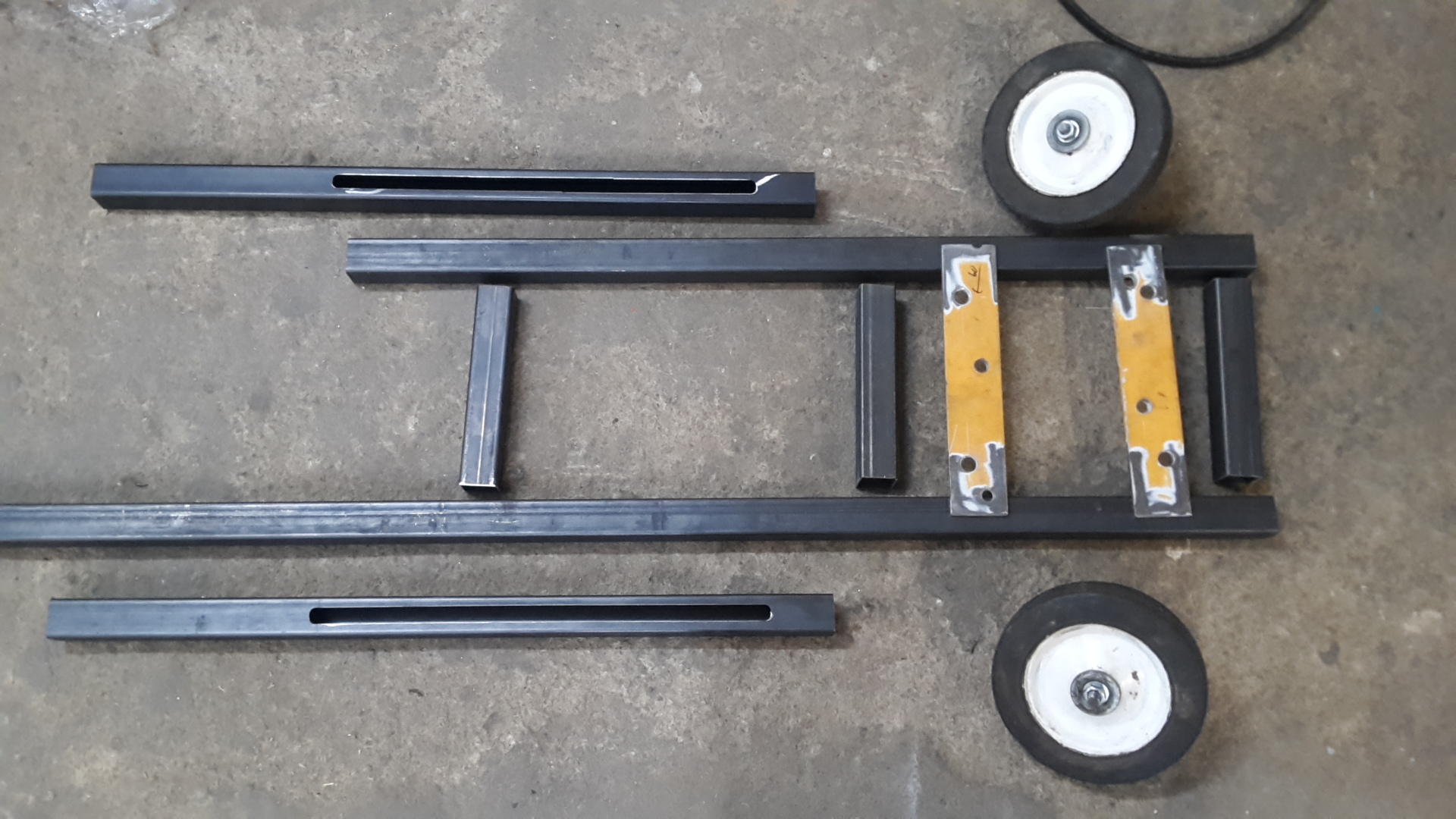
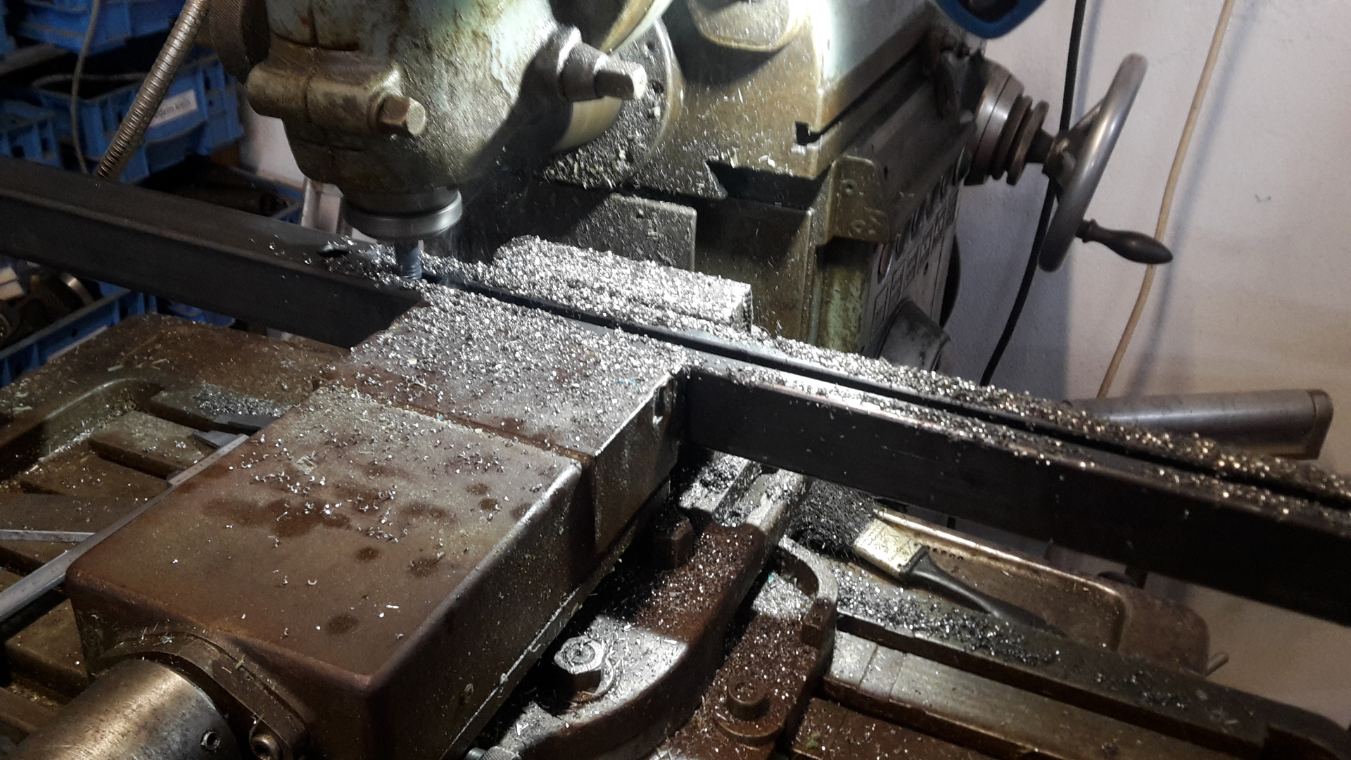
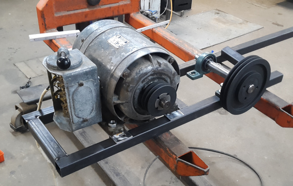 Motor mount is being positioned on the frame
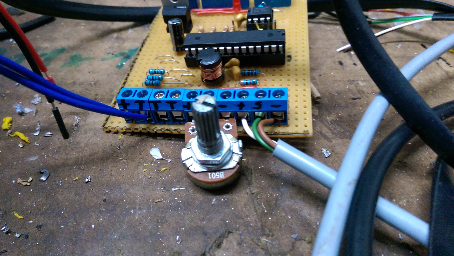
Control
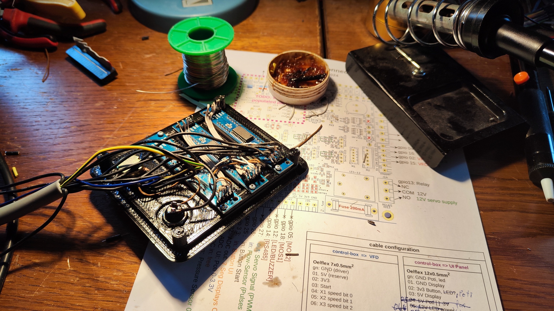
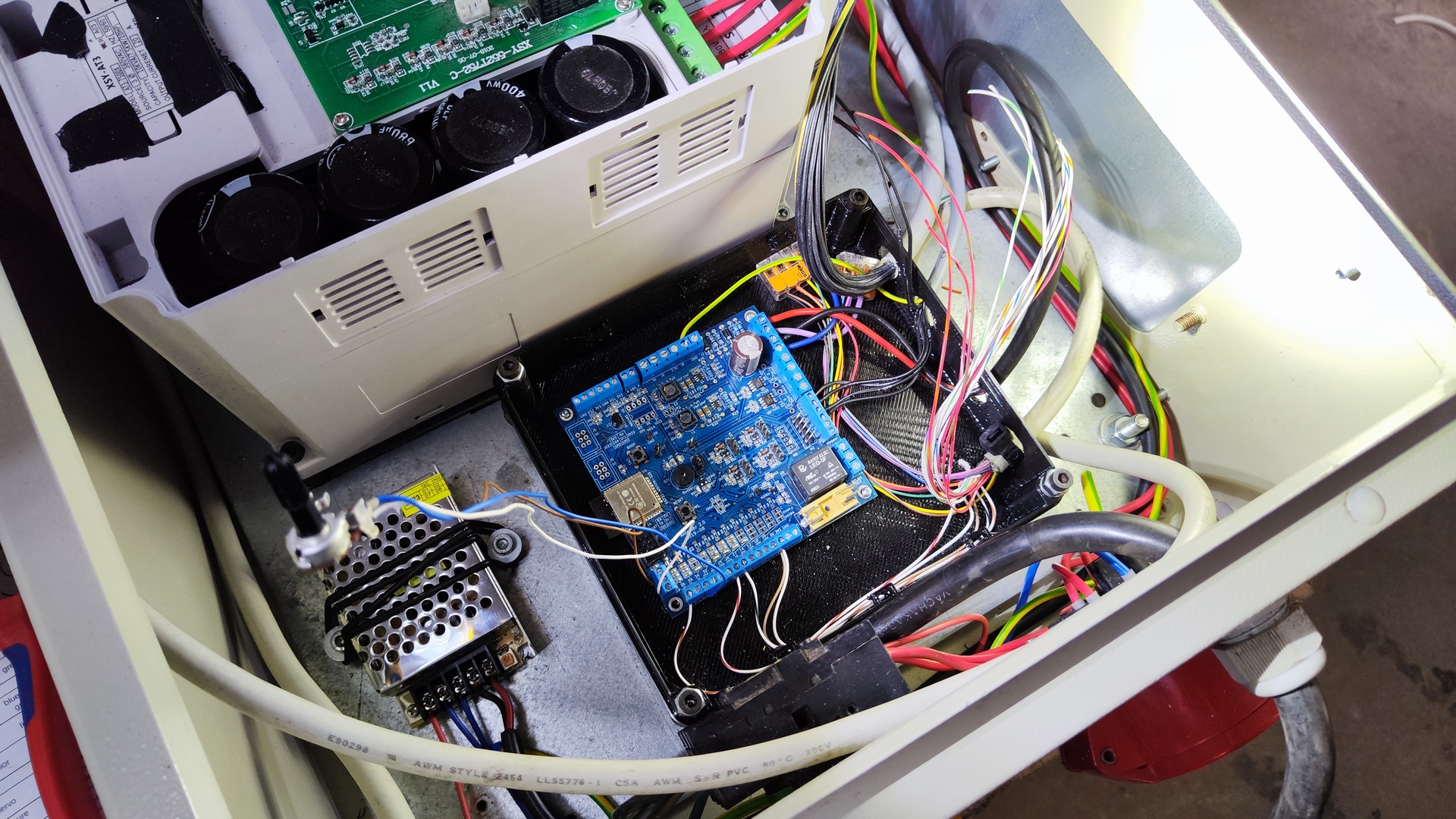
- Controller: Custom pcb with ESP-32 microcontroller
- Switching power supply: 12 V, 2 A
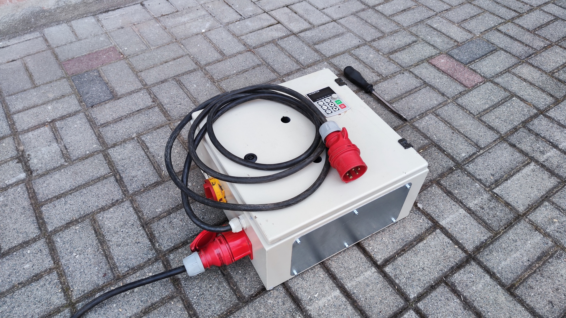
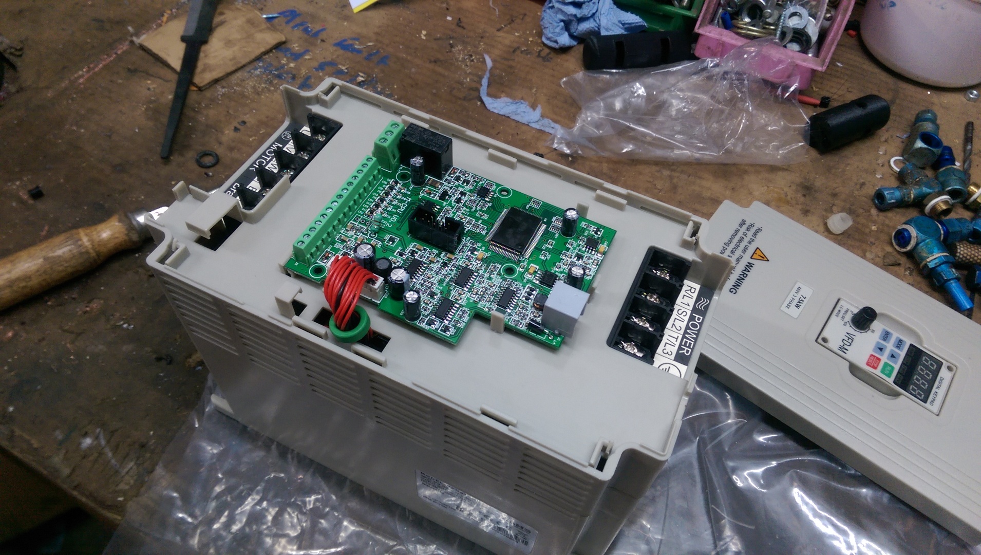
- VFD: 7.5 kW variable frequency drive
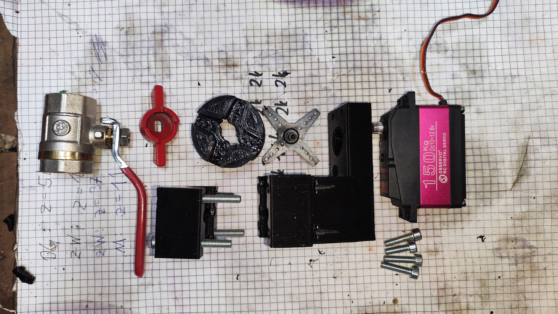
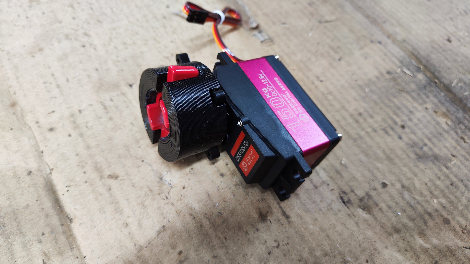
- Servo motor: DS51150-12V 150 kg
- Pressure sensor: Analog 5 V, 0-34.5 bar (500 psi)
- Flow sensor: Size 2”, 5-24 V, 10-200 L/min, 12 Pulses per Liter
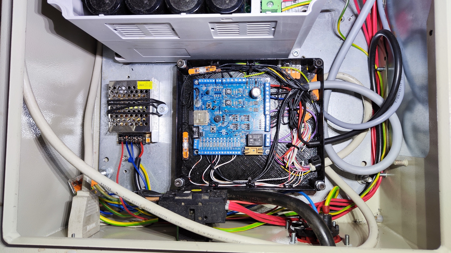
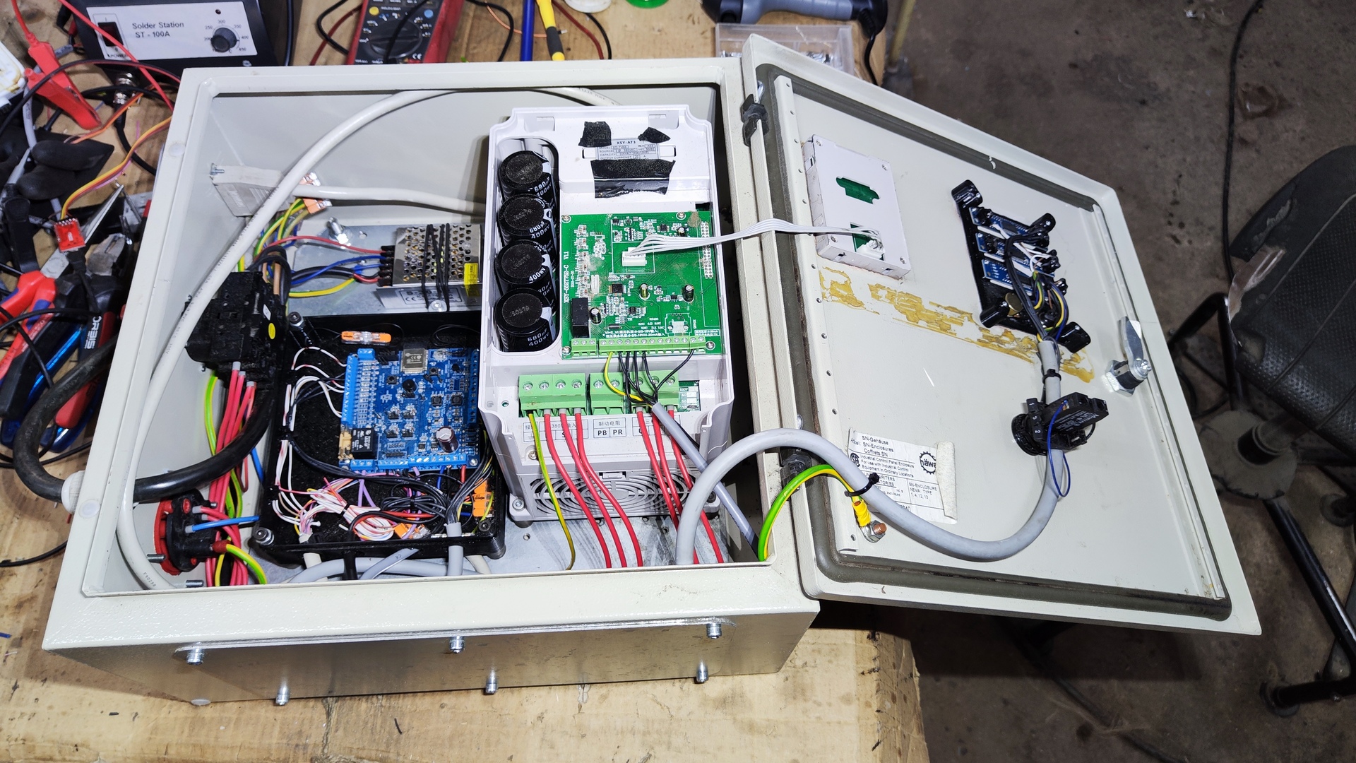
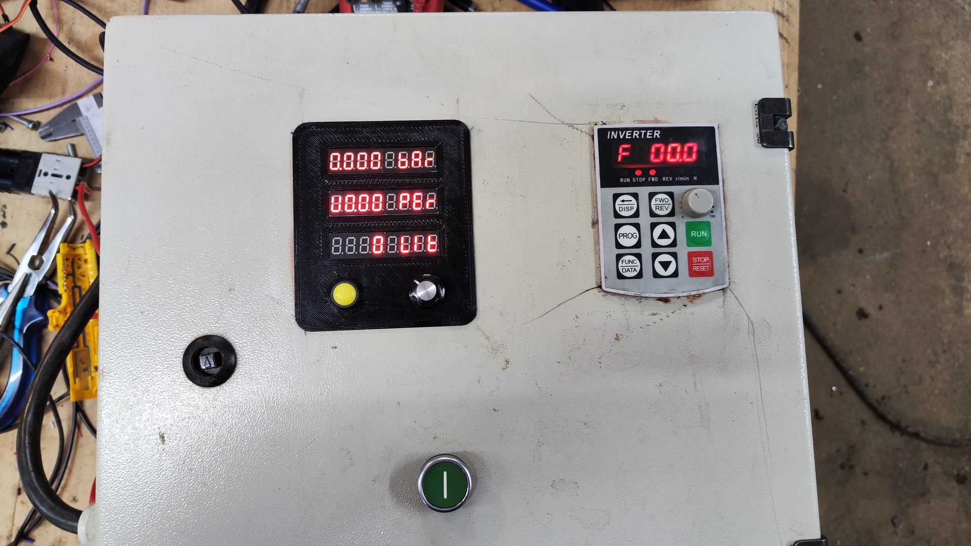
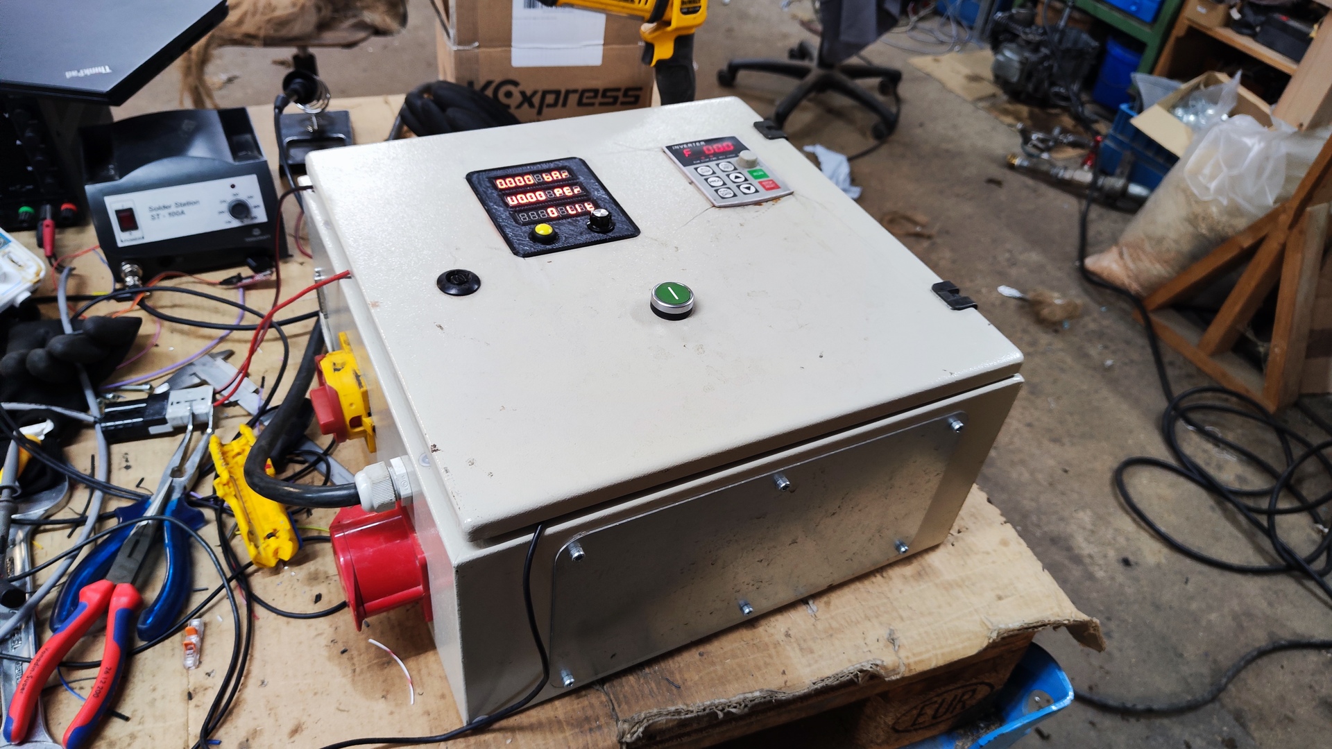
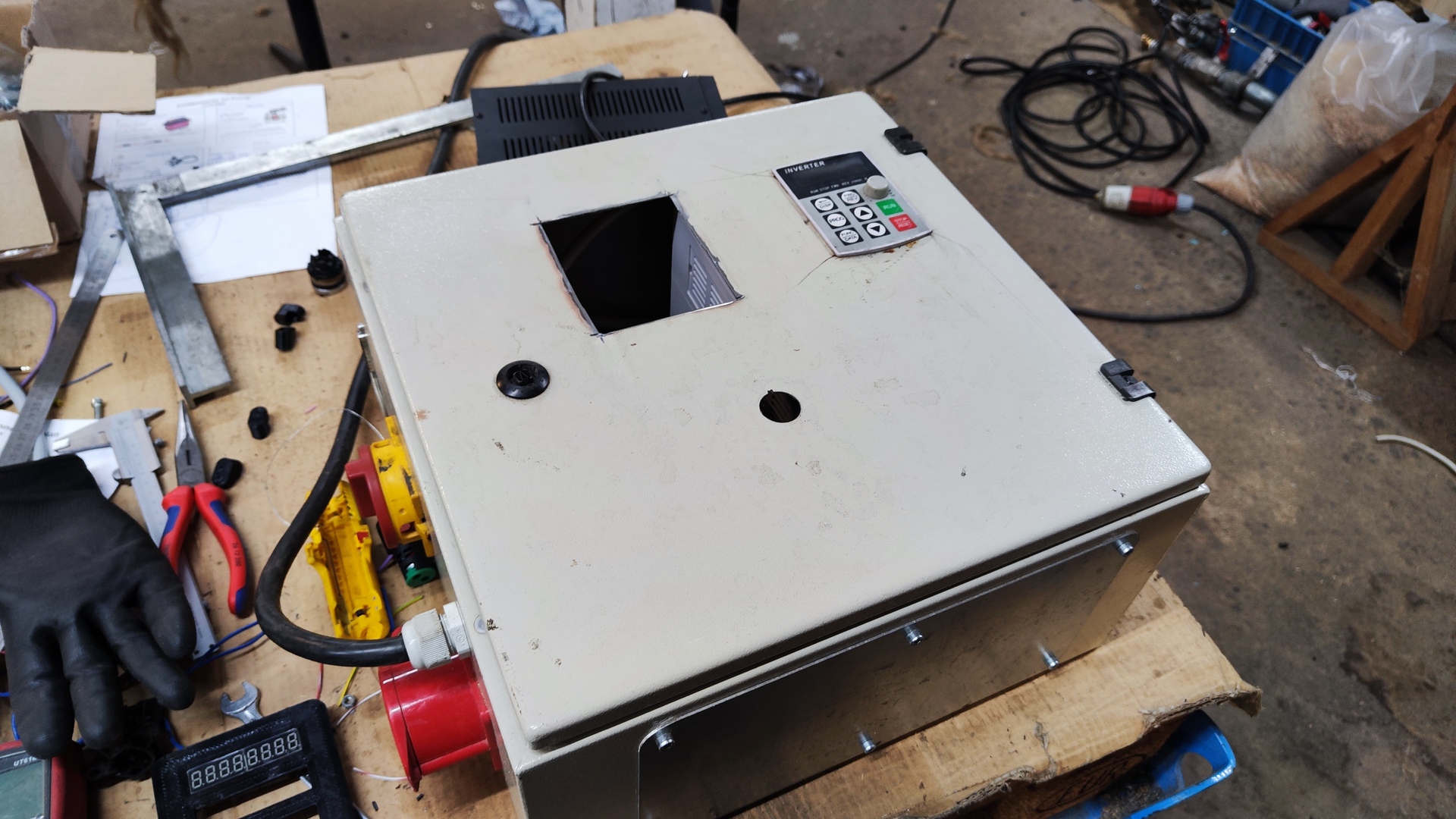
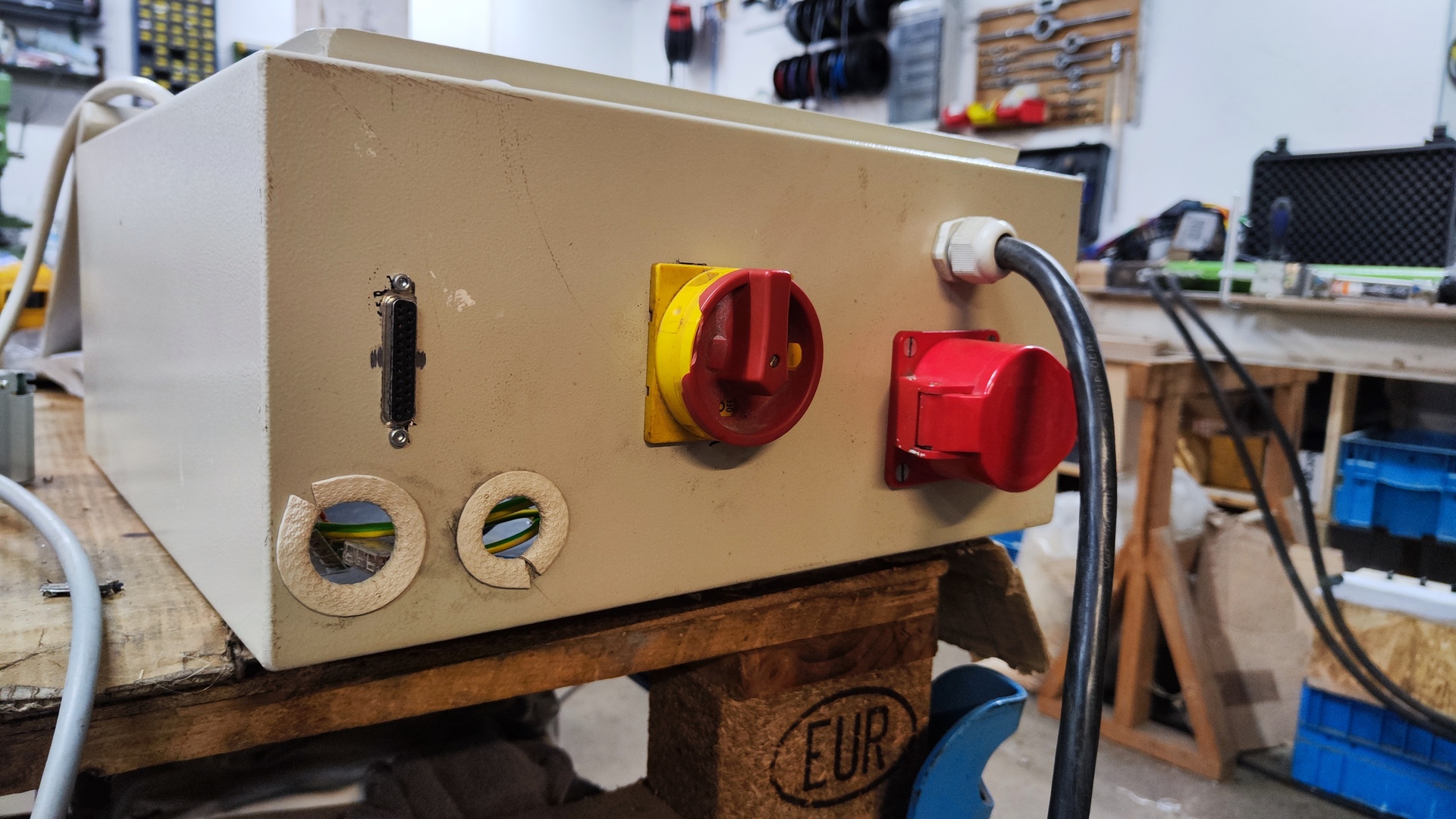
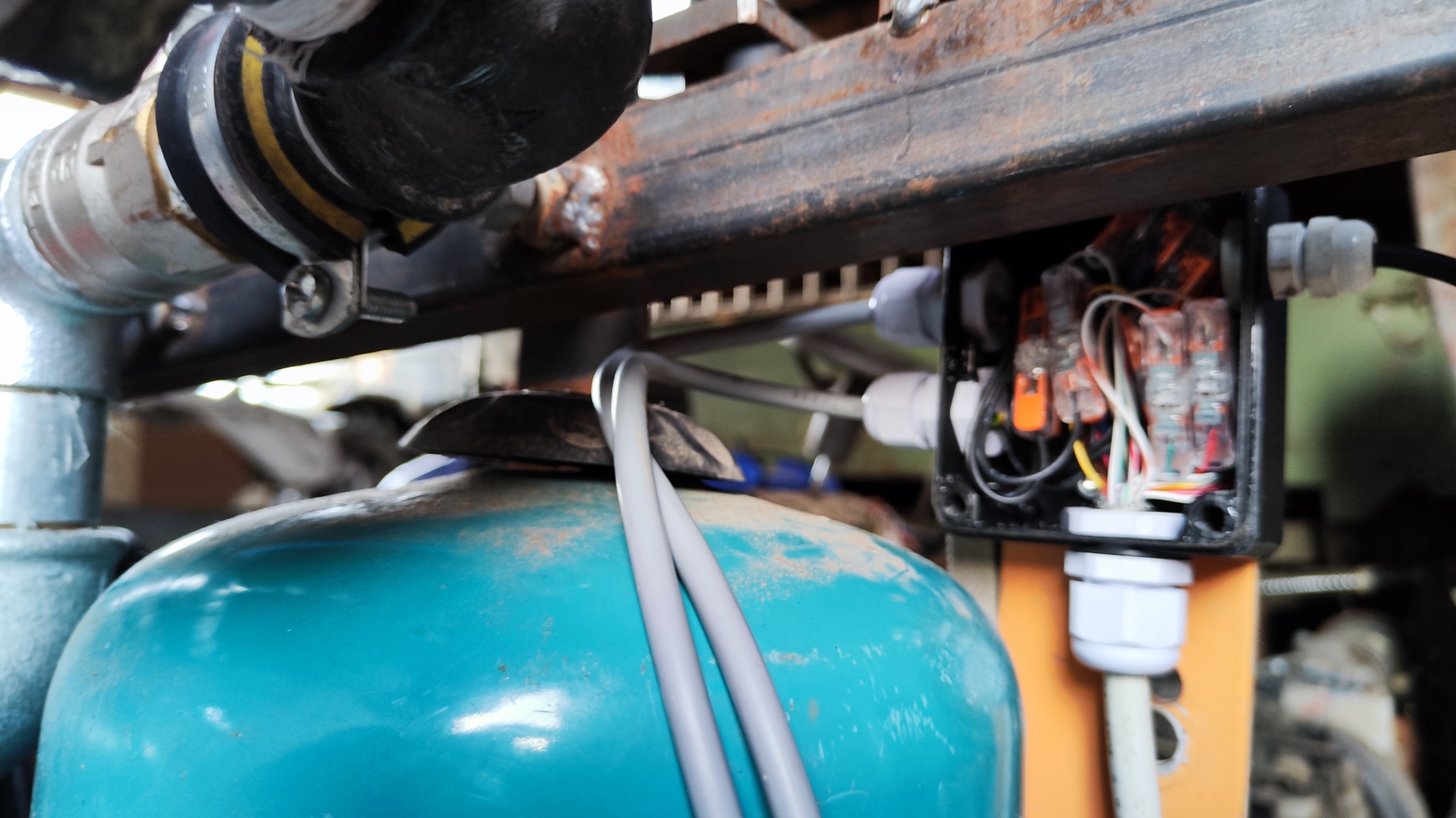
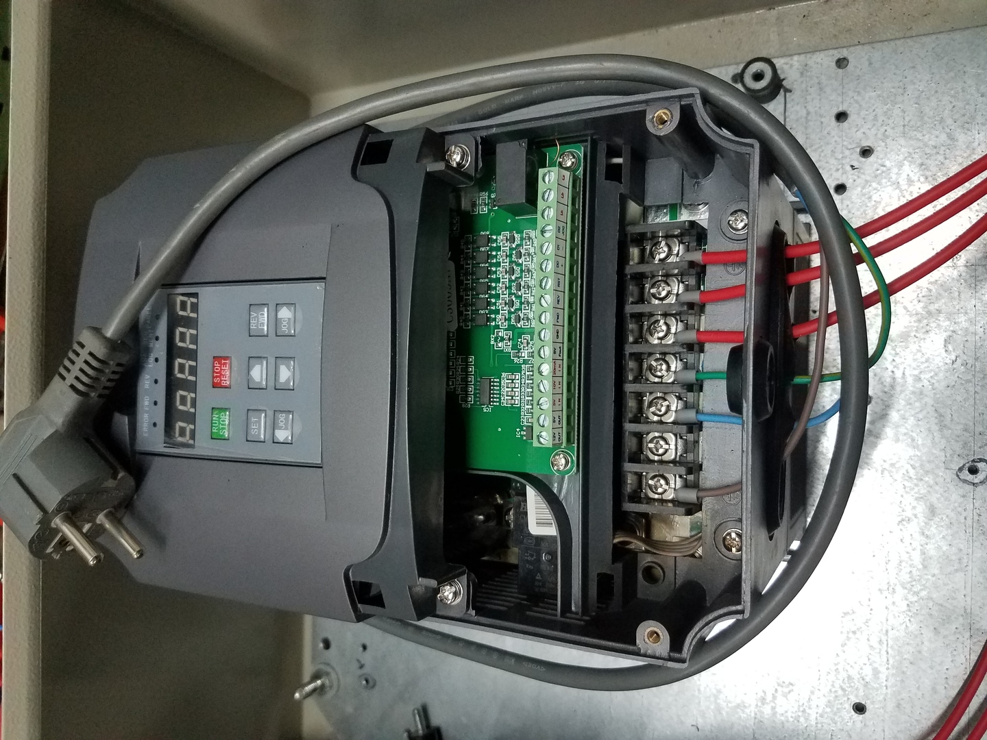
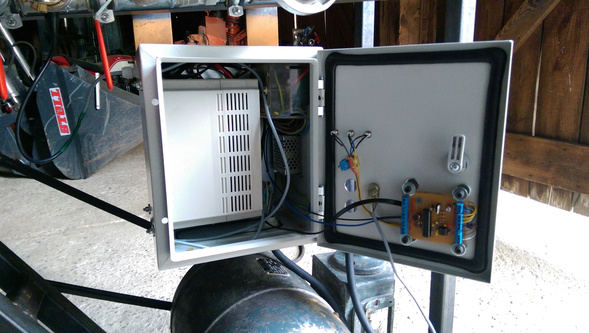
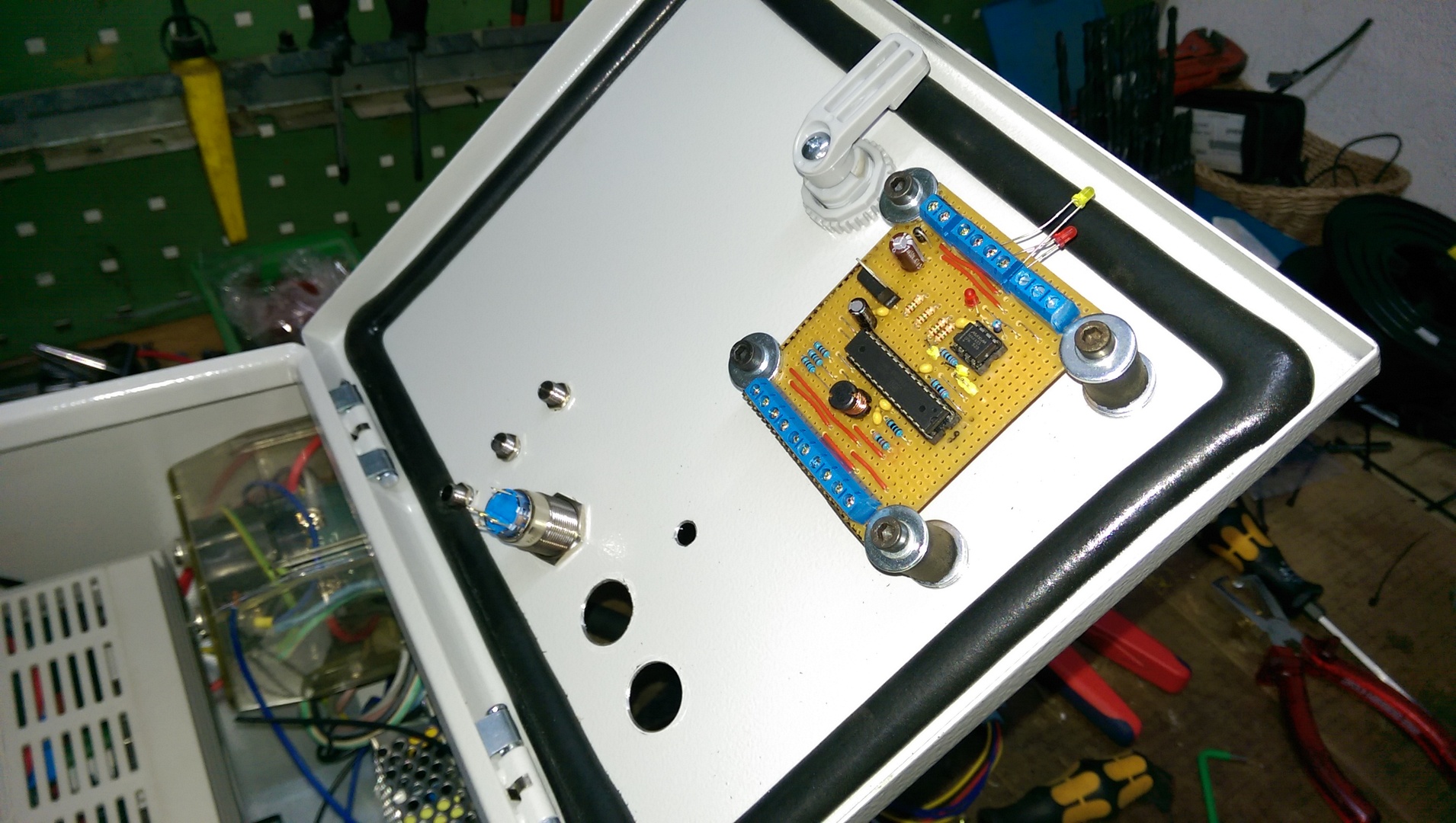
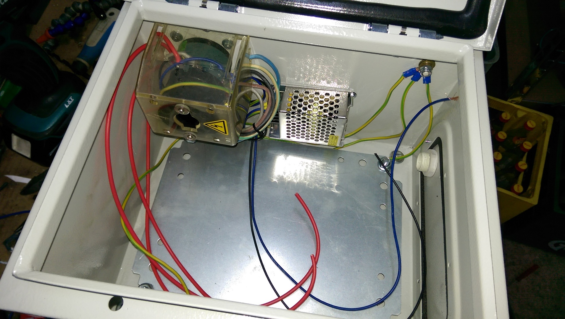
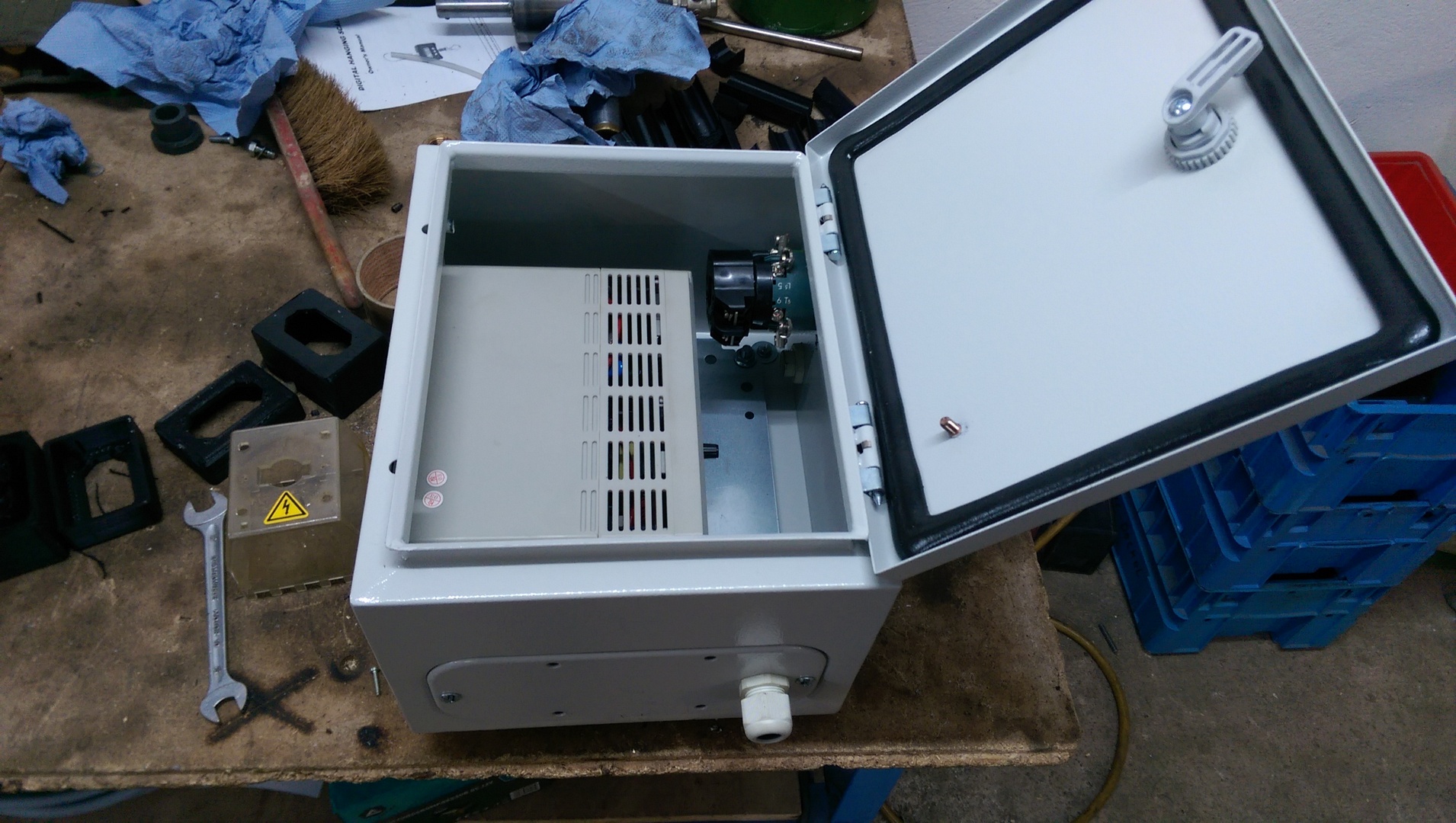
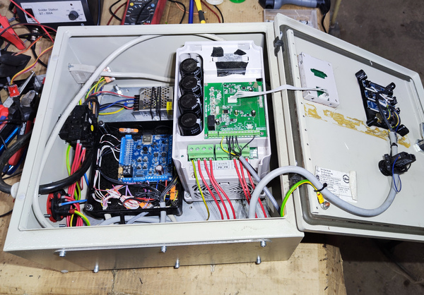 Open control cabinet with power supply, custom pcb, VFD and Display
Features
- Regulation
- Speed Control: Automatically adjusts motor speed to match the water demand using the VFD
- Pressure Regulation: Maintains consistent pressure output using PID control manipulating the bypass valve with a servo motor
- User Interface
- Hardware Interface:
- Start/stop and set target pressure using buttons
- View sensor data on 7 segment display
- Web Interface:
- Control pump remotely
- View data history
- Hardware Interface:
- Smart Control
- Auto Power Down: Enters power-saving mode during inactivity
- Dynamic pressure: Reduces Pressure when no water is used
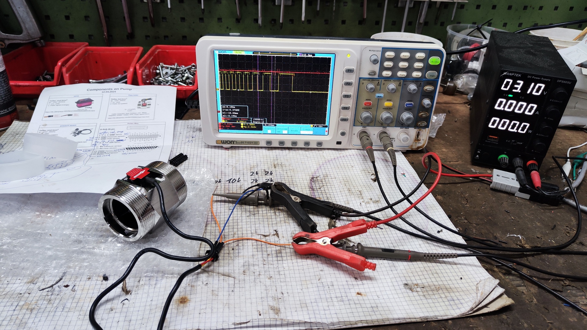
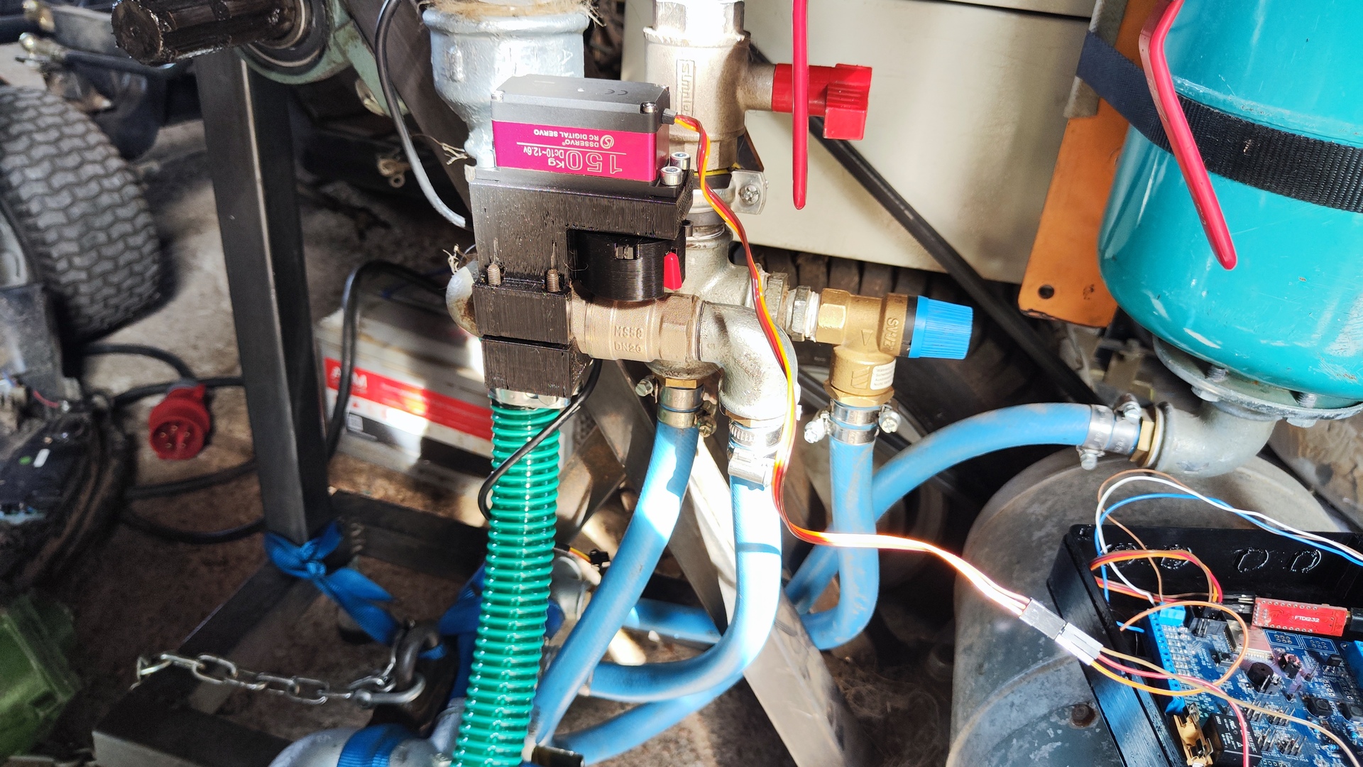
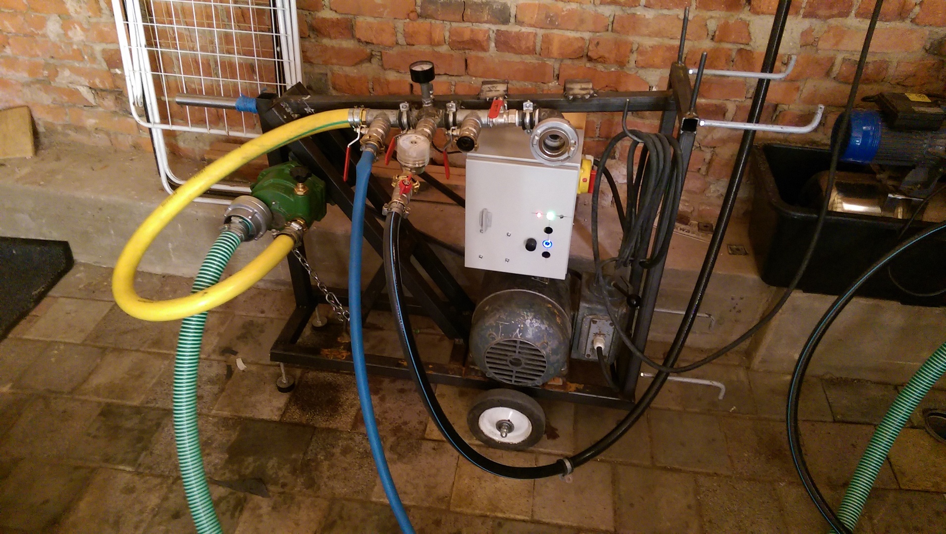
 First test with servo controlling the bypass valve
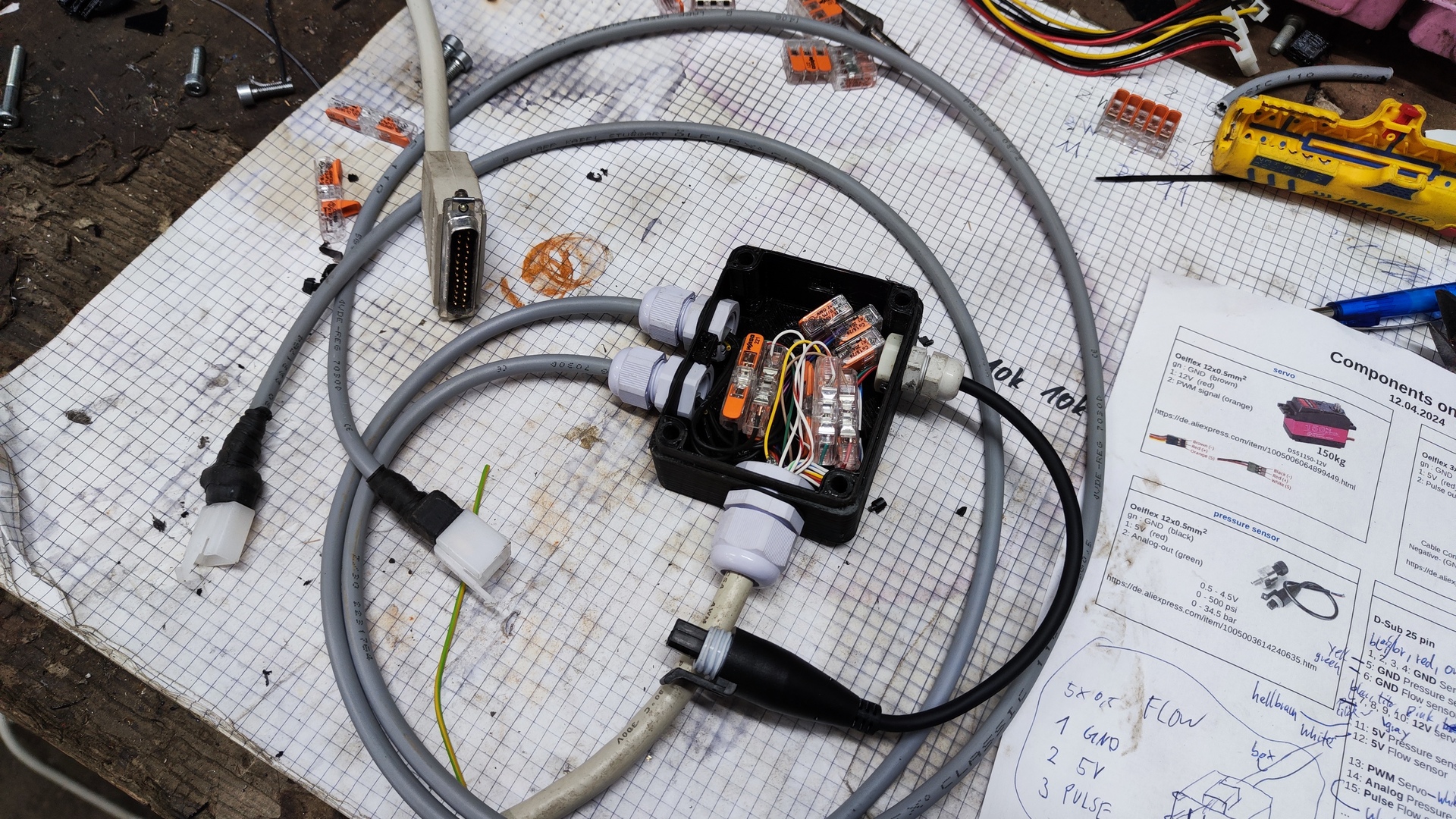
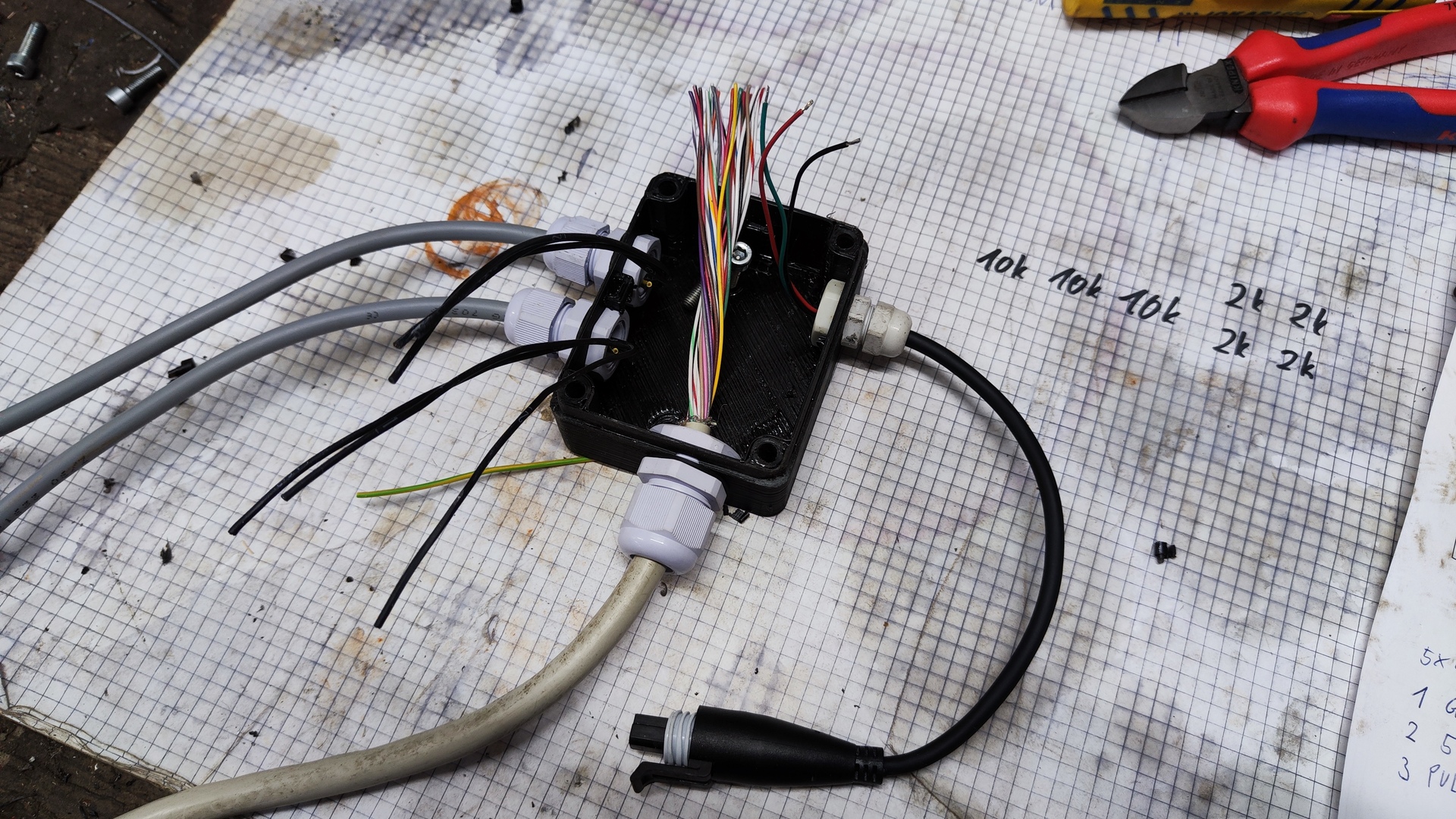
Electrical overview
All electrical aspects were planned in the following document:


Complete Document
Firmware
The firmware for the esp32 on the custom pcb was created using the following components:
- Programming Language: C++
- Development Framework: ESP-IDF
- Flowchart Design: diagrams.net
- Version Control: Git
The repository with the source code and all relevant documents is available on GitHub
Videos
First test (motor, frame)
2018.05.11 - First test of the welded frame and old motor:
Test hardware UI
2024.05.21 - Set target pressure and start the pump using potentiometer and buttons:
Start with phone
2024.05.21 - Set target pressure, start and check data using the web interface:
Test valve, motor control
2024.05.21 - Motor speed and valve position are automatically adjusted to achieve the desired pressure while varying the water flow:
Gallery